Do you have a question about the Icom IC-25H and is the answer not in the manual?
Details on semiconductors, frequency coverage, resolution, stability, and usable conditions.
Specifications for output power, emission mode, modulation system, and microphone.
Specifications for receiving system, modulation acceptance, intermediate frequency, and sensitivity.
Overview of CPU control, band-edge detector, and frequency range capabilities.
Explanation of multi-purpose scanning and dual VFO system.
Details on RF amplifier, mixer, filters, sensitivity, and transmitter output power.
Instructions for checking the transceiver for shipping damage and identifying contents.
Guidance on choosing a suitable place for mounting the transceiver in a vehicle or fixed station.
Specifies DC power requirements, negative ground system, and voltage cautions.
Importance of a good antenna for communication performance and VSWR adjustment.
Details on the supplied electret condenser microphone and wiring considerations.
Explains VFO/Memory Switch, VFO Switch, Tuning Control Knob, and indicators.
Connects the antenna to the set via a standard PL-259 connector.
Covers Scan/Stop, Simplex/Duplex, Volume, Squelch, and indicators.
Details on speaker/power connectors, memory backup, and internal scan controls.
How to tune, use the tuning control, and select VFOs or memory channels.
Explains how to set up simplex and duplex modes using switches for repeater access.
Step-by-step guide to programming desired frequencies into memory channels.
How to recall frequencies stored in memory channels.
How to scan through memory channels and between programmed frequencies.
Covers scanning the entire band and how scan functions resume after stopping.
Setting up and performing basic receiving operations with the transceiver.
Instructions for simplex and duplex transmitting operations.
Diagram and labels for components on the main circuit board.
Diagram and labels for components on the PLL circuit board.
Overview of PLL circuit, receiver, and transmitter signal paths.
Details on receiver circuitry, IF stages, audio, and squelch circuits.
Explains transmitter, oscillator, modulation, and audio frequency circuits.
Describes mixer, driver, power amplifier, ALC, and metering circuits.
Details power supply, local oscillator, and mixer/LPF/amplifier circuits.
Explains divider, reference frequency, phase detector, and VCO unit circuits.
Details clock pulse generation and scan/mic UP/DOWN control.
Explains signal paths (00-A0, 02-A0 etc.) for various functions like VFO, Memory, Scan.
Details signal flows for Duplex, Offset, Scan modes, and Power ON status.
Explains frequency control, display, and input/output operations.
Troubleshooting for power, sound, sensitivity, RF output, and modulation issues.
Troubleshooting for contact issues, lost memory, scan function failures, and scan stop.
| Brand | Icom |
|---|---|
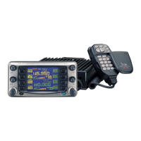
| Model | IC-25H |
| Category | Transceiver |
| Language | English |