Do you have a question about the Icom IC-24AT and is the answer not in the manual?
Critical warnings regarding electrical hazards and misuse of the transceiver.
Information on how to order replacement components for the transceiver.
Essential precautions and guidelines for safe and effective transceiver repair.
Visual layout and component identification of the transceiver's main internal board.
Visual layout and component identification of the transceiver's logic unit board.
Explanation of the VHF receiver circuit functionality and components.
Explanation of the UHF receiver circuit functionality and components.
Description of the VHF transmitter circuit's operation and constituent parts.
Details on the UHF transmitter circuit's design and operational principles.
Overview of Phase-Locked Loop circuits for frequency control in the transceiver.
Description of the logic circuits, including CPU port allocations and functions.
Explanation of the transceiver's power supply and battery charging circuits.
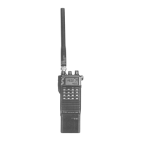
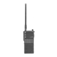
Identification and layout of parts on the transceiver's front panel.
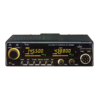
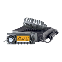
Identification and layout of parts on the transceiver's rear panel.
Listing and identification of optional accessories available for the transceiver.
Required test equipment and connection setup for transceiver adjustments.
Step-by-step procedure for adjusting the transceiver's PLL circuits.
Procedures for adjusting receiver sensitivity and S-meter calibration.
Procedures for adjusting transmitter output power and deviation settings.
Layout diagrams for the keyboard and PTT unit components.
Top view layout of the logic unit board with component identification.
Diagrams showing initial matrix configurations for different transceiver versions.
Layout diagram for the Adença unit and its connection to the logic unit.
Layout diagrams for the VR, UHF SW, and PRT units.
Top view layout of the main unit board with component identification.
Layout diagrams for the AF, MIC, and REG unit boards.
Layout diagrams for the APC and IO unit boards.
Layout diagrams for the DET and UHF YGR unit boards.
Layout diagrams for VHF/UHF RF and COL unit boards.
Layout diagrams for VHF/UHF PLL and VCO unit boards.
Layout diagrams for the LPF and HPF unit boards.
| Type | Handheld Transceiver |
|---|---|
| Modulation | FM |
| Channels | 10 |
| Current Drain | 1.5A |
| Weight | 350 g (with battery) |