3-4
UHF
TRANSMITTER
CIRCUITS
3-4-1
MIC
AMP CIRCUIT (MIC
UNIT)
This is
the same
as the
one commonly
used with the VHP
transmitter
circuit.
See
Section
3-3-1
for details.
3-4-2
MODULATION
CIRCUIT
(U*PLL UNIT)
The audio
signal from the MIC UNIT (UMOD) changes the
reactance of a diode(03)to modulate the oscillated signal at
the VCO
(Q11).
The oscillated signal
is
amplified
at the
buffer
amplifiers
(Q2,
Q3
on the U«PLL UNIT
and
Q7 on the
MAIN UNIT)
and
is
then applied to
the drive
amplifier circuit
on the APC
UNIT.
3-4-3
DRIVE AND POWER
AMPLIFIER
CIRCUITS
(APC
AND
U*YGR UNITS)
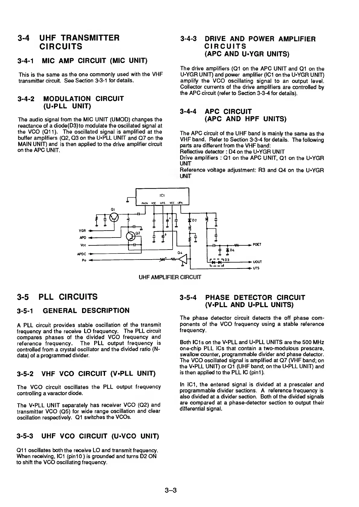
The drive
amplifiers
(Q1
on the APC UNIT and
Q1 on the
U*YGR UNIT)
and power amplifier (IC1
on the U*YGR
UNIT)
amplify the
VCO oscillating signal
to an output
level.
Collector currents
of the drive amplifiers
are controlled by
the APC circuit (refer
to Section
3-3-4
for
details).
3-4-4
APC
CIRCUIT
(APC AND HPF UNITS)
The APC circuit of
the UHF band is mainly
the same
as the
VHP band. Refer
to Section
3-3-4
for details.
The following
parts
are different from the
VHP band:
Reflective
detector
: D4 on the U*YGR UNIT
Drive amplifiers :
Q1 on the APC UNIT,
Q1 on the
U*YGR
UNIT
Reference
voltage
adjustment: R3 and
Q4 on the
U*YGR
UNIT
3-5
PLL
CIRCUITS
3-5-1
GENERAL
DESCRIPTION
A
PLL
circuit provides stable
oscillation
of the
transmit
frequency and the
receive LO frequency.
The PLL
circuit
compares
phases of the
divided VCO
frequency
and
reference
frequency.
The PLL
output frequency
is
controlled from a
crystal
oscillator and the
divided
ratio (N-
data) of a
programmed divider.
3-5-2
VHF
VCO
CIRCUIT
(V*PLL
UNIT)
The VCO
circuit
oscillates the PLL
output
frequency
controlling a
varactor
diode.
The
V*PLL
UNIT
separately has
receiver
VCO
(02)
and
transmitter
VCO
(05)
for
wide range
oscillation
and clear
oscillation
respectively. 01
switches
the
VCOs.
3-5-3
UHF
VCO CIRCUIT (U*VCO UNIT)
Q1 1
oscillates
both
the
receive LO and transmit frequency.
When receiving,
IC1 (pinlO
)
is
grounded
and turns D2 ON
to shift
the
VCO oscillating frequency.
3-5-4
PHASE DETECTOR CIRCUIT
(V-PLL AND U*PLL UNITS)
The phase detector circuit detects the off phase com-
ponents of the VCO
frequency using a stable reference
frequency.
Both ICIs on the V-PLL
and U*PLL UNITS are the 500 MHz
one-chip PLL ICs
that contain a two-modulous prescare,
swallow
counter,
programmable divider and phase detector.
The VCO
oscillated signal is amplified at
07
(VHP band;
on
the V*PLL UNIT) or
Q1
(UHF band; on the U-PLL UNIT)
and
is then applied to
the
PLL 1C
(pini ).
In IC1, the
entered signal is divided at
a
prescaler
and
programmable divider sections. A
reference
frequency is
also divided at a divider section. Both of the divided signals
are compared at a phase-detector section to output their
differential signal.
3-3