3-6-4
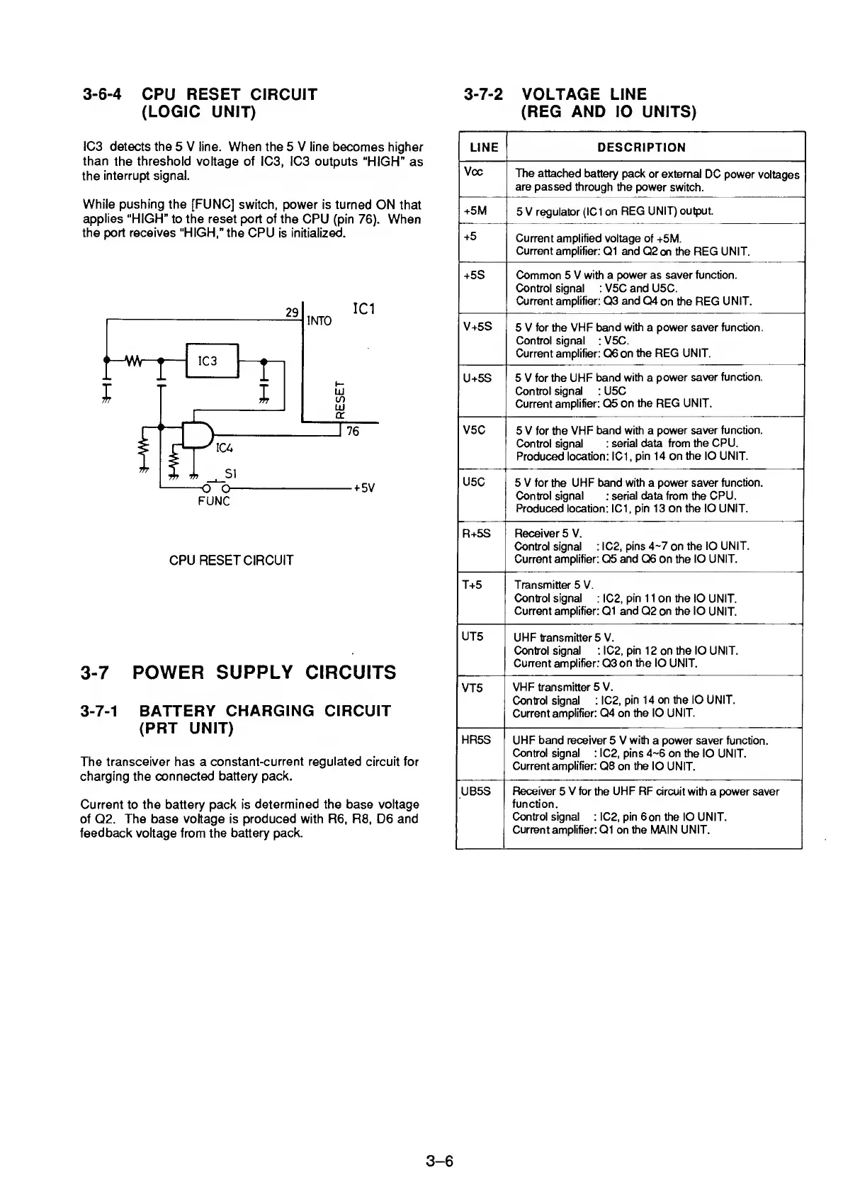
CPU RESET CIRCUIT
(LOGIC UNIT)
IC3 detects the
5 V line. When the 5 V line becomes
higher
than
the threshold voltage of ICS, ICS outputs
“HIGH” as
the
interrupt signal.
While pushing the [FUNC]
switch, power is turned
ON that
applies
“HIGH” to the reset port of the
CPU (pin
76).
When
the port receives “HIGH,” the
CPU is initialized.
CPU
RESET
CIRCUIT
3-7
POWER SUPPLY CIRCUITS
3-7-1
BATTERY
CHARGING CIRCUIT
(PRT UNIT)
The transceiver has a
constant-current regulated circuit for
charging the connected battery pack.
Current to the battery pack is
determined the base voltage
of
Q2. The base voltage is produced with R6, R8, D6 and
feedback voltage
from
the battery pack.
3-7-2
VOLTAGE LINE
(REG AND lO UNITS)
LINE DESCRIPTION
Vcc
The attached
battery pack
or external
DC power
voltages
are passed
through the power
switch.
+5M
5 V regulator
(IC1 on
REG
UNIT) output.
+5
Current
amplified voltage of
+5M.
Current amplifier:
Q1 and
Q2 on the REG UNIT.
+5S Common 5 V
with a power as saver function.
Control signal : V5C and U5C.
Current amplifier:
C33
and
04
on the REG
UNIT.
V+5S
5 V
for
the
VHF band with a power saver function.
Control signal
:
V5C.
Current
amplifier:
06 on
the
REG UNIT.
U+5S
5 V for the
UHF band
with
a
power
saver function.
Control signal : U5C
Current
amplifier: 05
on the REG UNIT.
V5C
5 V for the VHF
band with a
power saver
function.
Control signal
: serial data from
the CPU.
Produced
location: IC1
,
pin 14 on the lO UNIT.
U5C
5 V for the UHF band with a power saver
function.
Control signal
:
serial data from the CPU.
Produced location:
IC1, pin 13 on the lO UNIT.
R+5S Receiver 5 V.
Control signal
:
IC2, pins
4~7
on
the lO
UNIT.
Current
amplifier: 05
and 06
on the
lO UNIT.
T+5
Transmitters V.
Control signal
: IC2,
pin
1
1
on the 10
UNIT.
Current amplifier:
01
and
02 on
the
lO
UNIT.
UTS
UHF transmitter 5 V.
Control signal : IC2,
pin
12 on the lO UNIT.
Current amplifier: 03
on the
lO UNIT.
VT5
VHF
transmitter 5 V.
Control signal :
IC2,
pin 14
on
the lO UNIT.
Current
amplifier:
04
on
the 10 UNIT.
HR5S
UHF band receiver
5 V
with
a power saver function.
Control signal
: IC2, pins
4-6
on the
lO UNIT.
Current amplifier: 08 on the
lO UNIT.
UB5S
Receiver
5
V for the UHF RF
circuit with a power saver
function.
Control signal
:
IC2, pin
6on the lO UNIT.
Current
amplifier: 01 on the MAIN UNIT.
3-6