3-6-2
I/O
EXPANDER
1C
PORT
ALLOCATIONS
IC1
(lO
UNIT)
PORT
No.
PIN
No.
TERMINAL
NAME
DESCRIPTION
Q17 4
VCPC
Outputs
power
saver
signal
to
cut the
loop
filter from
the
VHP PLL
1C.
Q18 5
UCPC
Outputs
power saver signal
to cut the loop
filter from the
UHFPLLIC.
Q19,
Q20
6,
7 P01,
P02
Output RF
output power
selecting signal.
Q21 14
V5C
Becomes
“LOW” when
selecting the
VHF band.
This
port is controlled
with
the
power save function.
Q22
13 U5C
Becomes
“LOW"
when
selecting
the UHF
band.
This
port is
controlled with
the power
saver function.
IC2
(lO
UNIT)
PORT
No.
PIN
No.
TERMINAL
NAME
DESCRIPTION
Oil 6
UBAN
Becomes “LOW" when the
UHF
band is selected.
012
7
TR5
Becomes
“HIGH” while
transmitting and “LOW"
while receiving.
Q14
13
VT5 Becomes “LOW" while
transmitting in the
VHF
band.
015
12
UTS Becomes “LOW"
while
transmitting
in
the
UHF
band.
016
11
T+5
Becomes “HIGH"
while
transmitting.
IC6 (LOGIC UNIT)
PORT
No.
PIN
No.
TERMINAL
NAME
DESCRIPTION
03
6
AFON
Becomes “HIGH” to
open
the
squelch for beep tone.
04 7 RMUT
Becomes “HIGH" to cut
the
AF signal while beep
tone emits.
05
14
MICM
Becomes “HIGH" to
mute
the microphone
input.
06
13 TXLED
Becomes “HIGH" to light
up DS4 in red while trans-
mitting.
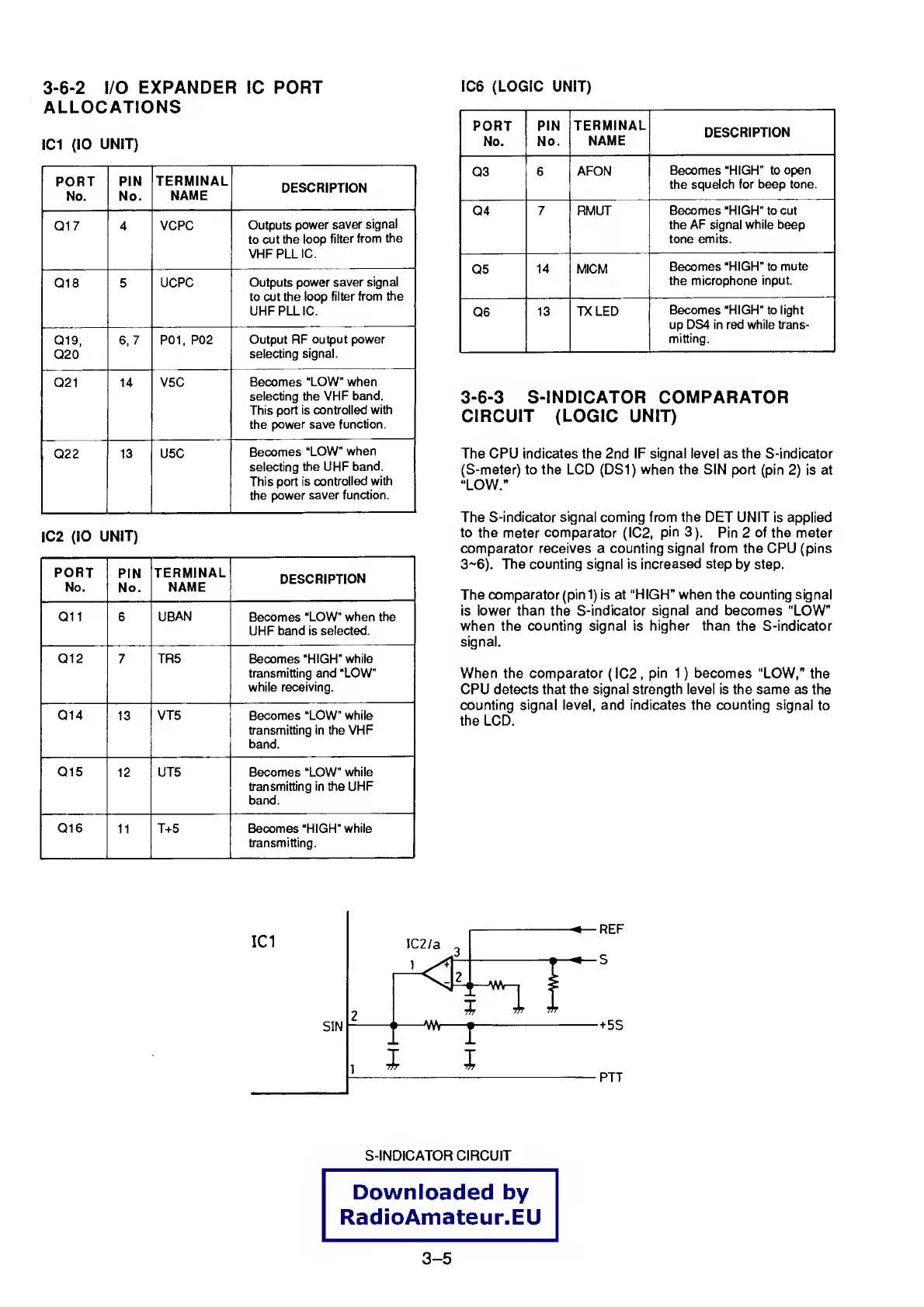
3-6-3
S-INDICATOR COMPARATOR
CIRCUIT (LOGIC UNIT)
The CPU indicates the 2nd IF
signal
level as the S-indicator
(S-meter) to the LCD (DS1) when the SIN port
(pin
2)
is at
“LOW.”
The
S-indicator signal coming from the
DET UNIT is applied
to the
meter
comparator
(IC2,
pin
3).
Pin 2 of the meter
comparator receives a counting signal from the CPU (pins
3-6). The counting signal
is increased step
by step.
The comparator (pin
1)
is
at
“HIGH” when the
counting signal
is
lower than the S-indicator
signal
and becomes “LOW”
when the
counting signal is higher than the S-indicator
signal.
When the
comparator
( IC2
,
pin
1
)
becomes
“LOW,” the
CPU detects that the signal strength
level
is the same as the
counting signal level, and indicates the counting signal
to
the LCD.
S-INDlCATOR CIRCUIT
Downloaded
by
RadioAmateur.EU
3-5