Do you have a question about the Icom IC-260E and is the answer not in the manual?
Overall transceiver specifications including semiconductors, coverage, resolution, and operating conditions.
Details transmitter output power, modulation, emission modes, and performance characteristics.
Outlines receiver sensitivity, selectivity, modes, and audio output parameters.
Explains microcomputer integration, band-edge protection, scanning, and dual VFOs.
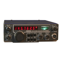
Details the continuous tuning system, LED display, and outstanding performance aspects.
Lists built-in features like Noise Blanker, CW Break-in, and APC for enhanced operation.
Instructions for unpacking, inspecting, and selecting a mounting location for the transceiver.
Covers power requirements, connections, and antenna considerations for installation.
Details on connecting microphones, external speakers, CW keys, and tuning knob adaptors.
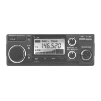
Identifies and explains primary front panel controls like mode, RIT, tuning, and scan/memory buttons.
Describes secondary controls including Tone Call, Tuning Speed, Noise Blanker, VFO/AGC, Volume, Squelch, and MIC connector.
Explains frequency display, indicators, meter, and rear panel connection sockets.
Details the Memory Switch, Power Socket, and accessory socket pin assignments.
Instructions on how to tune, manage preset frequencies, and understand frequency display by mode.
Covers VFO/Memory switching, VFO gang control, memory programming, and scanning functions.
Guides for operating in SSB, CW, and FM modes, including receiving and transmitting.
Information on using the IC-260A/E for satellite communication with frequency charts.
Labels and identifies internal components on the main unit, driver, and related boards.
Solutions for power, sound, sensitivity, modulation, and RF output problems.
Addresses issues with contact, frequency, scan operations, calibration, and memory.
Provides voltage measurements for transistors and ICs across Main, SSB, PLL, and Driver units.
Details R output timing charts and threshold level charts for CMOS and P-MOS ICs.
Illustrates the overall block diagram of the IC-260A/E's internal units and connections.
| Frequency Range | 144-146 MHz |
|---|---|
| Mode | FM |
| Power Output | 50 W |
| Voltage | 13.8V DC |
| Type | Mobile Transceiver |
| Weight | 1.3 kg |
| Sensitivity | 0.25 μV (12 dB SINAD) |