5 - 3
ADJUSTMENT ITEM ADJUSTMENT CONDITIONS OPERATION VALUE
144 MHz BAND
TRANSMIT OUTPUT
POWER
(HI POWER)
(Band
Low)
[L PHL]
1•
•
Connect an RF Power Meter to the
antenna connector (J1).
Transmitting
Rotate the right band’s [DIAL] to
adjust the transmit output power,
then push the right band’s [MAIN
•BAND] key during transmit.
50 W
(Band
High)
[L PHH]
2
(MID POWER) (Band
Low)
[L PML]
3 15 W
[others]
22 W
[TPE-01]
(Band
High)
[L PMH]
4
(LOW POWER) (Band
Low)
[L PLL]
5 5 W
(Band
High)
[L PLH]
6
430 MHz BAND
TRANSMIT OUTPUT
POWER
(HI POWER)
(Band
Low)
[R PHL]
1•
•
Connect an RF Power Meter to the
antenna connector (J1).
Transmitting
Rotate the right band’s [DIAL] to
adjust the transmit output power,
then push the right band’s [MAIN
•BAND] key during transmit.
50 W
(Band
High)
[R PHH]
2
(MID POWER) (Band
Low)
[R PML]
3 15 W
[others]
22 W
[TPE-01]
(Band
High)
[R PMH]
4
(LOW POWER) (Band
Low)
[R PLL]
5 5 W
(Band
High)
[R PHH]
6
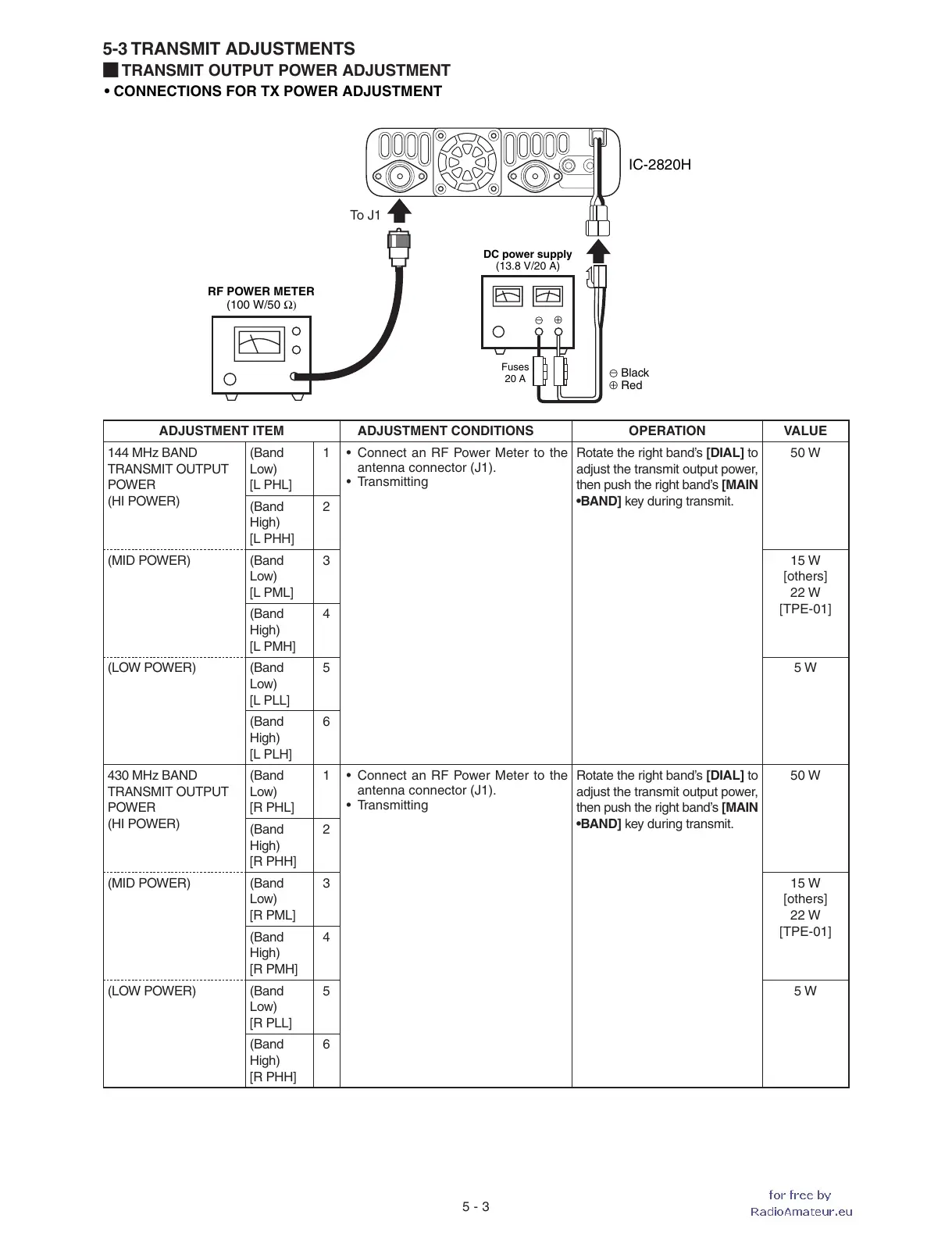
• CONNECTIONS FOR TX POWER ADJUSTMENT
RF POWER METER
(100 W/50 Ω)
Fuses
20 A
DC power supply
(13.8 V/20 A)
⊕
−
To J 1
IC-2820H
Black
Red⊕
−
5-3 TRANSMIT ADJUSTMENTS
¤ TRANSMIT OUTPUT POWER ADJUSTMENT
 Loading...