Do you have a question about the Icom IC-281H and is the answer not in the manual?
Critical safety warnings regarding voltage, environment, power supply, and RF signal limits.
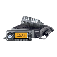
Key operational parameters including frequency coverage, power requirements, dimensions, and weight.
Technical details of the transmitter, including output power levels, modulation, and frequency deviation.
Technical details of the receiver, including sensitivity and intermediate frequencies.
Detailed explanation of the receiver's signal path, including filters, amplifiers, and mixers.
Detailed explanation of the transmitter's signal path, including modulation and power amplification.
Procedures for adjusting receiver sensitivity and the S-meter for optimal performance.
Procedures for adjusting transmitter output power and frequency deviation.
| Frequency Range | 144-148 MHz |
|---|---|
| Modes | FM |
| Dimensions | 6.1 x 7.5 x 2.5 inches |
| Weight | 2.9 lbs |
| Supply voltage | 13.8 VDC |
| Type | Mobile |