Do you have a question about the Icom IC-32E and is the answer not in the manual?
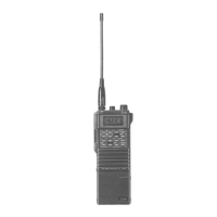
Enables operation on both VHF and UHF bands from your palm.
Allows simultaneous transmit and receive operations on VHF and UHF bands.
Provides 5.5W on VHF and 5W on UHF band with specific battery packs.
Features 20 memory channels and 2 CALL channels for storing operational data.
Includes full band, programmed, memory, and priority watch scan functions.
Equipped with MAIN DIAL and KEYBOARD for rapid frequency and memory selection.
Rubber gaskets protect the casing from water splashes.
Notifies user of incoming subaudible tones identical to programmed ones.
Reduces current flow when no signal or operation is detected for 30 seconds.
Used for frequency operations across all bandwidths with two VFOs for VHF and UHF.
Used for operating the transceiver using stored memory channel contents.
Used for operating on a programmed CALL channel for VHF and UHF bands.
Used for programming subaudible tone, tuning steps, scan edges, and power saver.
Describes controls located on the top panel of the transceiver.
Turns the transceiver ON/OFF and adjusts audio output level.
Sets the threshold point for the squelch to quiet noise.
Changes frequency and memory channel; performs dial select function.
Allows selection of high or low RF output power.
Port for connecting the transceiver's antenna.
Connector for an optional external speaker or earphone.
Connector for an optional external microphone.
Port for connecting an external 12-15V DC power source.
Details controls and indicators on the front of the transceiver.
Lights up to indicate when the transceiver is transmitting.
Displays operating status, frequency, and mode indicators.
Audio output for received signals.
Input for voice transmission.
Details controls located on the side of the transceiver.
Opens squelch to monitor signals; also tone squelch.
Selects secondary functions of keys or dial.
Push-to-talk button for transmitting.
Activates the backlight for the FUNCTION DISPLAY.
Releases the battery pack from the transceiver.
Explains various indicators shown on the transceiver's function display.
Shows the current operating frequency.
"TS" blinks when tuning step setting is active in SET mode.
Displays "M" when the transceiver is in MEMORY mode.
Shows the selected memory channel number.
Indicate semi-duplex ("DUP") or simplex ("-DUP") operation.
Displays "SPT" during full duplex operation.
"PROG" blinks during programmed scan or scan edge settings.
"PRIO" appears when priority watch is active.
"T" for tone encoder, "SQL" for pocket beep, "T SOL" for tone squelch.
"SKIP" indicates a memory channel is programmed for skipping.
Shows signal strength or RF output power level.
"TO" blinks during subaudible tone setting in SET mode.
"OW" blinks during offset frequency writing in SET mode.
Flashes '((()))' when a matching subaudible tone is received.
Displays "L" when the key lock function is activated.
Describes the main functions of each key on the transceiver's keypad.
Used for direct frequency entry or memory channel selection.
Change frequency, start full band or memory scan.
Selects VFO, stops scans, clears input.
Selects MEMORY mode, changes channel by 10.
Selects VHF or UHF band.
Selects CALL CHANNEL mode or previous mode.
Explains secondary functions accessed by pressing FUNCTION + key.
Turns the subaudible tone encoder ON/OFF.
Controls optional tone squelch or pocket beep functions.
Programs a memory channel as a skip channel.
Selects simplex, -duplex, or +duplex modes.
Enters the SET mode for parameter programming.
Initiates the priority watch function.
Selects digits for dial select function in VFO mode.
Turns the beep tone function ON/OFF.
Starts programmed scan in VFO mode.
Starts selected band memory scan in MEMORY mode.
Transfers memory contents to VFO or CALL channel.
Writes VFO contents to memory or CALL channel.
Selects or cancels full duplex operation.
Activates or deactivates the key lock function.
Instructions for charging the transceiver's battery pack.
Procedure to detach the battery pack from the transceiver.
Details on connecting chargers or power sources for battery charging.
Important warnings regarding battery handling, fire, water, and short circuits.
Provides approximate operation times for different battery packs under various conditions.
Explains the Battery Memory Effect for NiCd batteries and proper charging.
Guide for connecting the supplied antenna to the transceiver.
Instructions for attaching the handstrap clip and holder.
Steps for attaching the belt clip to the transceiver's rear panel.
Methods for setting operating frequencies using the main dial, keys, or digit keys.
How to set frequency by rotating the main dial in VFO mode.
How to change frequency using UP/SCAN and DN/SCAN keys.
How to enter frequencies directly using the numeric keypad.
Procedure to select frequency digits using the dial select function.
Steps for receiving signals, including power, squelch, frequency, and monitor functions.
Steps for transmitting, including power, mode, and using the PTT switch.
How to operate the transceiver with repeaters, including offset frequencies.
Specific procedures for repeaters controlled by subaudible tone, DTMF, or 1750Hz tone.
Methods to select memory channels using the main dial or dial select function.
Selecting memory channels by rotating the main dial.
Selecting memory channels using the dial select function.
Selecting memory channels sequentially using UP/SCAN and DN/SCAN keys.
Selecting specific memory channels using the numeric keypad.
Procedure to store frequency and other data into memory channels.
How to copy memory contents to VFO for signal searching.
How to read and program call channels for quick access.
Steps to recall and display call channel information.
Procedure to store frequency and data into call channels.
How to transfer call channel contents to VFO mode.
Scans repeatedly between upper and lower edges of VHF or UHF band.
Scans between user-programmed frequency edges within a band.
Scans programmed memory channels, skipping designated channels.
Scans programmed memory channels within the same band, skipping designated channels.
How to program a memory channel to be skipped during scans.
Monitors a priority channel while in VFO operation.
Watches a memory channel while operating in VFO mode.
Switches between VFO frequencies on different bands for monitoring.
Monitors a call channel while operating in VFO mode.
Monitors memory channels while operating in VFO mode.
Allows simultaneous transmitting on one band and receiving on another.
How to set up full duplex operation using the transceiver's VFOs.
Storing transmit and receive frequencies for full duplex in memory channels.
Using memory channels to perform full duplex operations.
Using memory channels for VHF/UHF simplex frequencies instead of offset frequencies.
Activating pocket beep or tone squelch functions using an optional unit.
Turning the key beep tone ON or OFF.
Preventing accidental changes to frequency or settings.
Overview of parameters programmable in SET mode: tones, offsets, steps, scans, power saver.
Visual guide for navigating and accessing SET mode parameters.
Programming subaudible tone frequencies for repeater access.
Setting transmit frequency offset for semi-duplex operations.
Selecting the frequency tuning step increment (e.g., 5kHz, 12.5kHz).
Programming start and end frequencies for programmed scans.
Enabling or disabling the power saver function for data communications.
Common problems and their solutions for transceiver operation.
Information on backup battery life and replacement.
Procedure to reset the transceiver's CPU to clear settings or resolve errors.
Procedure to change minimum tuning steps for the VHF band.
Procedure to change minimum tuning steps for the UHF band.
Covers frequency coverage, mode, tuning steps, impedance, power supply, and dimensions.
Details output power, modulation, deviation, emissions, and microphone impedance.
Details receiving system, IF, sensitivity, squelch, and audio output.
| Brand | Icom |
|---|---|
| Model | IC-32E |
| Category | Transceiver |
| Language | English |