TRANSMITTER
ADJUSTMENT
(CONTINUED)
ADJUSTMENT
ADJUSTMENT CONDITIONS
MEASUREMENT
VALUE
ADJUSTMENT
POINT
UNIT
LOCATION
UNIT ADJUST
SWR
DETECTOR
1
•
Displayed
frequency: 14.10000 MHz
•
Mode : USB
• [RF
PWR] control : Max. CW
•
Connect a
jumper wire
between R87
front side and ground.
»
•
Appiy an RF signai to the
[MIC]
connector.
Level
: 10 mV/
1.5
kHz
•
Transmitting
Rear
panel
Connect
the RF
power meter to
the
antenna
connector.
100 w
Front
panel
[MIC]
control
2
MAIN
Connect the
DC
voltmeter
to
J6
pin 2.
Minimum
FILTER
1
3
After adjustment, remove the
jumper wire
from
R87.
TRANSMIT
GAIN
1
•
Dispiayed
frequency: 14.10000 MHz
•
Mode : USB
• [RF
PWR] controi : Max. CW
•
Appiy an AF signai to the
[MiC]
connector.
Level
:1 mV/1.5 kHz
•
Transmitting
Rear
panel
Connect the
RF
power meter to
the
antenna
connector.
Pre-set to
max. CCW.
MAIN R85
50 W
Front
panel
[MIC]
control
Maximum
level
MAIN
L37, LI
7,
L16, L14,
L7
2 •
[MIC]
control : Max. CW
50
W
R85
NOTE: Adjust
the
[MIC]
control to keep the output
power at
50
W for
each
adjustment.
OUTPUT
POWER
1
•
Displayed frequency: 1.91000 MHz
•
Mode : CW
• [RF
PWR] control
: Max.
CW
•
Connect a key to
the [KEY] jack and
keep the key down.
Rear
panel
1
Connect the
RF
power meter to
the
antenna
connector.
Pre-set
to
max'. CCW.
MAIN
i
R194,
R241
2
100 W
R210
3 •
[RF PWR]
control : Max. CCW
10 W
R208
1
Repeat steps 2 and 3 a
couple of times.
Ic APC
1
•
Displayed frequency: 14.10000 MHz
•
Mode : CW
•
[RF PWR] control : Max. CW
•
Connect a jumper wire
between
J6
pin
3
and ground.
•
Connect a key to the [KEY] jack and
keep the key
down.
Rear
panel
Connect
the
ammeter between
the AC
power supply
and
IC-725.
22 A
MAIN R194
2
After adjustment, remove the
jumper wire from
J6
pin 3.
Po
METER 1
•
Displayed frequency: 14.10000 MHz
•
Mode : CW
•
[RF
PWR] control :
Max.
CW
•
Connect
a
key
to
the [KEY] jack and
keep the key down.
Front
panel
Meter
100
%
(full
scale)
MAIN
R186
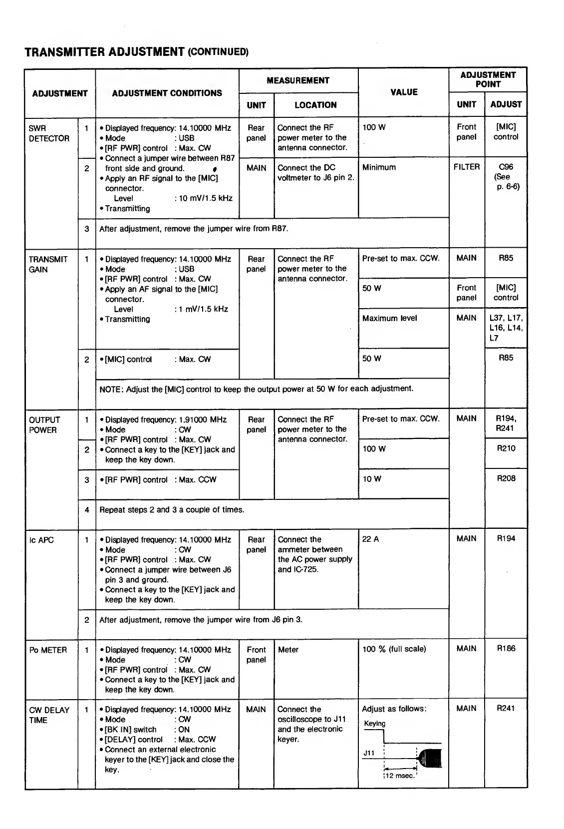
CW DELAY
TIME
1
•
Displayed frequency: 14.10000 MHz
•
Mode : CW
•
[BK IN] switch :ON
•
[DELAY]
control
: Max.
CCW
•
Connect
an external electronic
keyer to the [KEY] jack and
close the
key.
MAIN
Connect the
oscilloscope to
J1
1
and
the
electronic
keyer.
Adjust as
follows:
Keying
112 msec.'
MAIN R241