August 2015
(Replacement page)
4-3
4-2 FREQUENCY ADJUSTMENT
Select an adjustment item using [
] / [
] keys, then set to the specifi ed value using [
] / [
] keys on the connected PC’s keyboard.
ADJUSTMENT ADJUSTMENT CONDITION OPERATION
ADJUSTMENT
ITEM/POINT
VALUE
VDD
Voltage
(RX)
1 • CH No. : [AM MID]
• Receiving
Connect a Digital voltmeter to the CP2
on the MAIN UNIT.
[F13]
(CS-A210/A220
ADJ)
13.5 V
±0.1 V
Lock Voltage
(RX)
1 • CH No. : [AM HIGH]
• Receiving
Connect a Digital voltmeter to the CP1
on the MAIN UNIT.
C136
(MAIN UNIT)
3.5 V
±0.1 V
(TX) 2 • CH No. : [AM HIGH]
• Transmitting
C127
(MAIN UNIT)
Lock Voltage
Verify
(RX)
1 • CH No. : [AM LOW]
• Receiving
Connect a Digital voltmeter to the CP1
on the MAIN UNIT.
(Verify)
More than
0.5 V
(TX) 2 • CH No. : [AM LOW]
• Transmitting
Reference
Frequency
1 • CH No. : [AM HIGH]
• Connect an RF Power Meter to
the antenna connector.
• Transmitting
Loose couple an Frequency Counter to
the antenna connector.
[F1]
(CS-A210/A220
ADJ)
136.975 MHz
(±500 Hz)
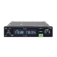
(TOP VIEW)
• VDD volatage (RX and TX) adjustments
VDD voltage (RX and TX) check point
CP2
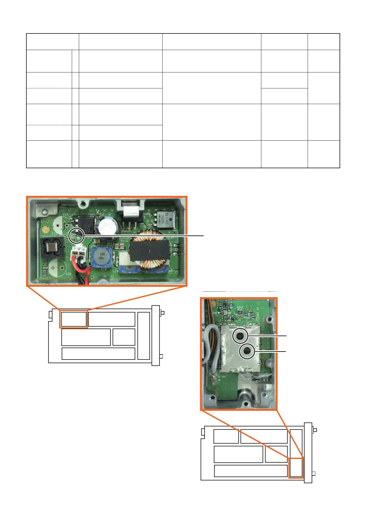
(TOP VIEW)
Lock voltage (TX)
adjust point
C127
Lock voltage (RX)
adjust point
C136