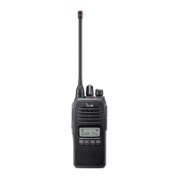
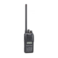
EasyManuals Logo

Icom IC-F14/S User Manual

Icom IC-F14/S
48 pages
To Next Page IconTo Next Page
To Previous Page IconTo Previous Page
Page #14 background imageLoading...
Page #14 background image
8
2
PANEL DESCRIPTION
LED indicator
The LED indicator indicates several informa-
tion as follows;
(Ref.; R=Red, G=Green, O=Orange)
R R R R
O O
O O
G G G G
G G
G G G G G G G G
R G R G R G R G R G R G R G R G
R O R O R O R O R O R O R O R O
G
G G
Clone Err
Clone T X/ RX
Low BATT 1
Low BATT 2
Busy
F/S Scan
Call LED Blink
Call LED ON
TX Low BAT T2
R
TX
TX: Turns Red while transmitting a signal.
• RX: Turns Green while receiving a signal.
• Call LED (ON): When receiving a matched 2/5-tone.
• Call LED (Blink): When receiving a matched 2/5-tone.
• Fast/Slow scan: Blinks while Fast/Slow scan is activated.
• Low BATT1: You should charge the battery. (blinks slowly)
• Low BATT2: You must charge the battery. (blinks fast)
TX low BATT2: Low BATT2 was detected during TX mode.
• CH err: Non-programmed channel is selected.

Other manuals for Icom IC-F14/S

Questions and Answers:

Question and Answer IconNeed help?

Do you have a question about the Icom IC-F14/S and is the answer not in the manual?

Icom IC-F14/S Specifications

General IconGeneral
BrandIcom
ModelIC-F14/S
CategoryTransceiver
LanguageEnglish

Related product manuals