SECTION 3 DISASSEMBLY AND OPTION INSTRUCTIONS
3 - 1
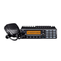
• Opening cover
Remove 4 screws from bottom cover.
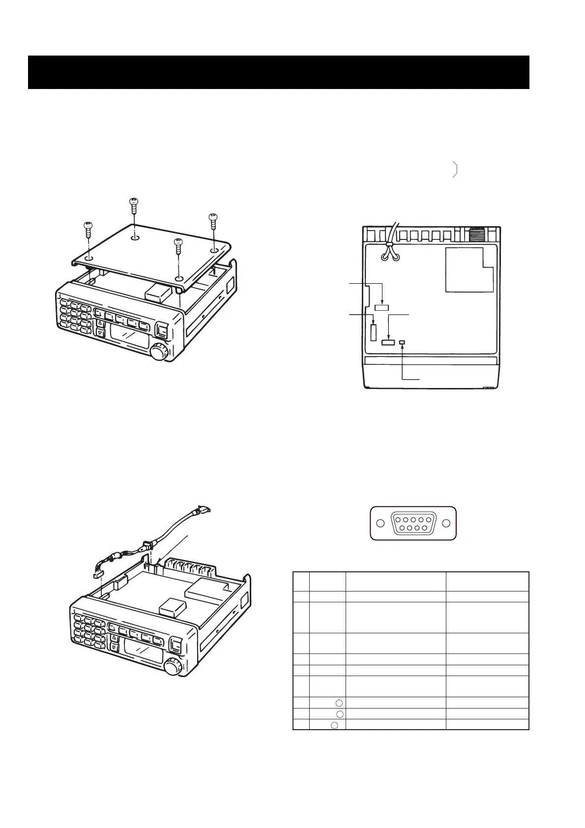
• OPC-617 connection
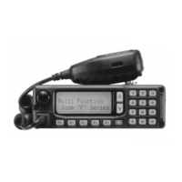
• Installation location
Install option units.
OPC-617 ACC CABLE: J4
UT-96 5-TONE UNIT
or UT-105 SmarTrunk II
TM
Logic Board
EX-1761 MEMORY EXPANSION UNIT: J7
OPC-822 INTERFACE CABLE: J501
PIN ASSIGNMENT
Break the jack plate using cutting pliers to connect the
OPC-617.
Pin
No.
Terminal
name
Description Specification
1 DIM Backlight control input +5 to +30 V for dark
2 PAAF
AF output for public
address and Ext SP func-
tions
0 to 330 mV rms/
47 kΩ
3 DISC
AF output for a terminal
unit
330 mV rms/100 kΩ
4 IN AF input for a terminal unit 330 mV rms/1200 bps
5 PTT PTT control input 0 V for transmit
6 HORN
Grounded when receiving
the specified call
Less than 50 mA
when grounded
7 PAAF – Ground for PAAF –––
8 DISC – Ground for terminal output –––
9 IN – Ground for terminal input –––
 Loading...