5 - 2
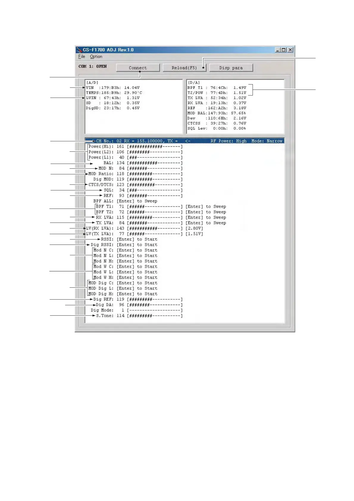
q: Transceiver's connection state
w: Reload adjustment data
e: Receive sensitivity measurement
r: Connected DC voltage measurement
t: PLL lock voltage measurement
y: Operating channel select
u: RF output power
i: FM modulation balance (narrow)
o: CTCSS/DTCS deviation
!0: Squelch level
!1: Reference frequency
!2: Receive sensitivity (automatic)
NOTE:
!3: PLL lock voltage for RX (automatic)
!4: PLL lock voltage for TX (automatic)
!5: PLL lock voltage for RX (manual)
!6: PLL lock voltage for TX (manual)
!7: S-meter adjustment
!8: Digital RSSI
!9: Deviation (narrow)
@0: Deviation (wide/middle)
@1: Deviation (digital)
@2: DSP frequency
@3: Base band frequency
@4: 2/5 TONE deviation
The above values for settings are example only.
Each transceiver has its own specific values for each setting.
r
t
y
u
q
i
o
!0
!2
!1
!3
!4
!5
!6
!7
w
e
o
!1
!8
!9
@1
@0
@2
@3
@4
• CS-F1700 ADJ'S SCREEN EXAMPLE
 Loading...