OPTIONS
• OPC-1132A, OPC-347 DC POWER CABLE
2 fuse holders are attached. USE only a 20 A fuse.
OPC-1132A: 3 m (9.8 ft)
OPC-347: 7 m (23 ft)
• OPC-1939, OPC-2078 ACC CABLE
Connects to an external terminal.
OPC-1939: D-sub 15-pin, an external level converter
(user supplied) is required.
OPC-2078: D-sub 25-pin, built-in level converter
• HM-152, HM-152T, HM-148G, HM-148T,
HAND MICROPHONE
HM-152: Hand microphone
HM-152T: DTMF microphone
HM-148G: Self ground heavy duty microphone
HM-148T: Self ground heavy duty DTMF microphone
• SM-26 DESKTOP MICROPHONE
• SP-30, SP-35, SP-35L EXTERNAL SPEAKER
Input impedance: 4 Ω
SP-30: Rated input: 20 W, Maximum input: 30 W
SP-35, SP-35L: Rated input: 5 W, Maximum input: 7 W
• UT-108R DTMF DECODER UNIT
Provides pager and code squelch capabilities.
• UT-109R/UT-110R VOICE SCRAMBLER UNIT
Non-rolling type (UT-109R) and Rolling type (UT-110R)
voice scrambler units provides higher communication
security.
ANTENNA
A key element in the performance of any communication
systems is the antenna. Contact your dealer for
information regarding antennas and how to install them.
FUSE REPLACEMENT
Fuses are installed in the supplied DC power cable. If a
fuse blows, track down the source of the problem, repair it,
and then replace the damaged fuse with a new rated one.
L Fuse rating: 20 A, 10 A*
* For the 25 W transceivers
NOTE: Use only specied fuses.
CLEANING
If the transceiver becomes dusty or dirty, wipe it clean with
a soft, dry cloth.
BASIC OPERATION
1
AF VOLUME CONTROL KNOB [VOL]
Rotate the knob to adjust the audio output level.
L Minimum audio level is preset.
2POWER KEY [ ]
Push to turn the transceiver ON or OFF.
L The following optional functions are available at
power ON:
• Automatic scan start
• Password prompt
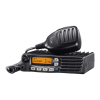
PANEL DESCRIPTION
NOTE: Dierent functions may have been assigned to the keys by your dealer, except for the Power key.
D Front panel
TX/RX
1 2 3 4
P0 P1 P2 P3
1
34 2
Speaker
Function indicators
D
Microphone
The supplied or optional microphone has a PTT switch
and a hanger hook.
L
The following functions are available when the
microphone is ON or OFF hook, depending on the
presetting:
•
Automatic scan starts when you put it ON hook.
•
Scan is cancelled when you take it OFF hook.
•
Scan is paused when you take it OFF hook.
•
Automatically selects the Priority channel when you
take it OFF hook.
•
Sets to the Inaudible mode (mute state) when you
put it ON hook.
•
Sets to the Audible mode (unmute state) when you
take it OFF hook.
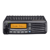
D Function indicators
TX/RX
1 2 3 4
1
3 2
1
CHANNEL INDICATOR
•
Indicates the operating channel.
•
Blinks when receiving a signal during a scan.
•
All indicators blink while entering the start up
password.
2
TX/RX INDICATOR
•
Lights red while transmitting.
•
Lights green while the channel is busy (receiving).
•
Blinks orange when the matching 2-tone or 5-tone
call is received.
•
Alternately blinks green and red when a
programming error has occurred.
3
ACTIVATED KEY INDICATORS (P0/P1/P2)
Lights when a assgined key function is activated.
NOTE:
When the supplied DC voltage is high, all
indicators blink. Check the DC voltage.
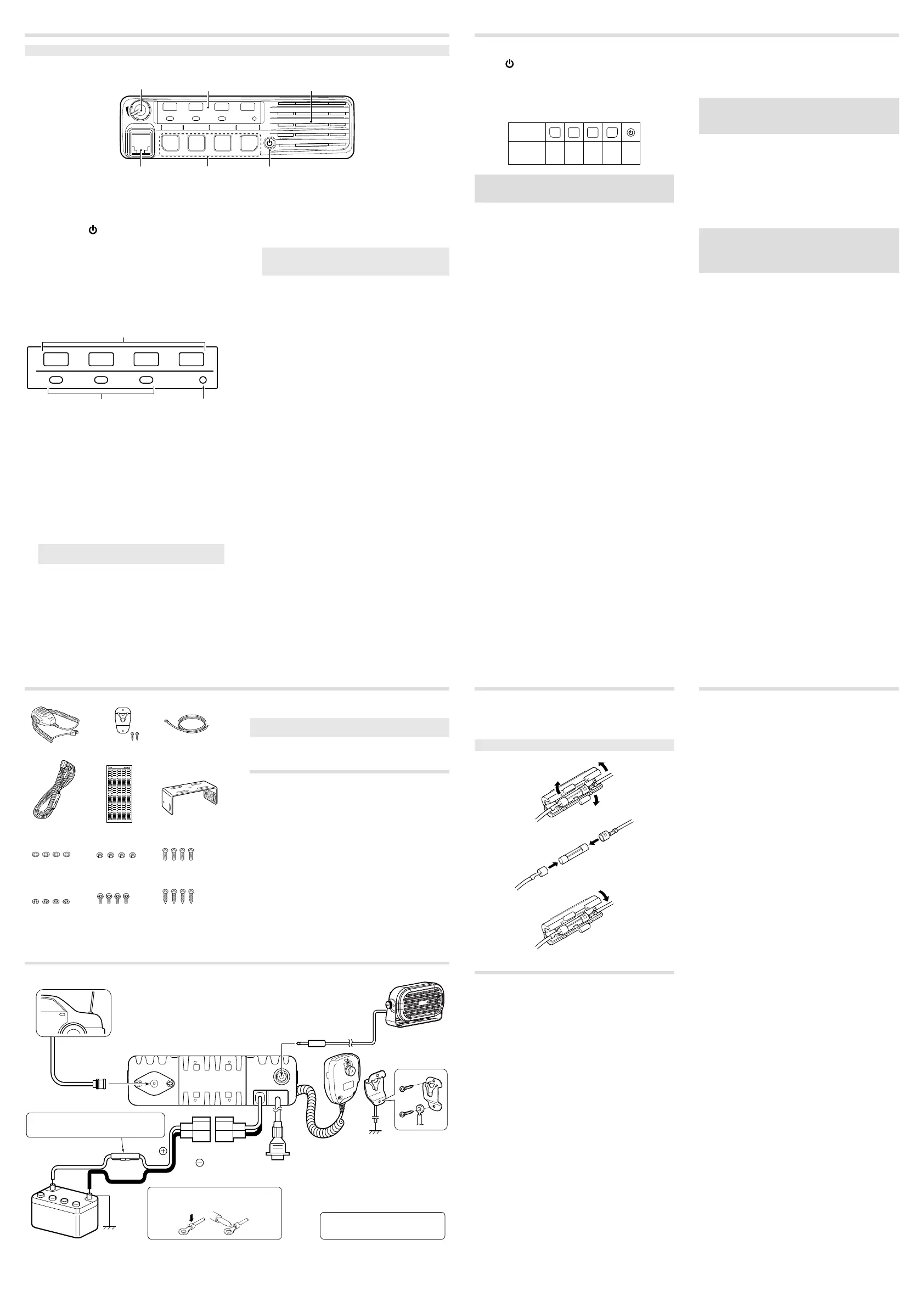
REAR PANEL CONNECTION
e
r
Black
Red
q
w
t
1
ANTENNA CONNECTOR
Connect to an antenna. Ask
your dealer about antenna
selection and placement.
4
OPTIONAL CABLE
(OPC-1939, OPC-2078)
Connect an external modem
or dimmer control.
5
DC POWER RECEPTACLE
Connect to a 12 V DC battery. Pay
attention to polarities.
3
MICROPHONE HANGER
Connect the supplied microphone
hanger to the vehicle’s ground
for microphone ON/OFF hook
functions.
2
EXTERNAL SPEAKER JACK
Connect to a 4 ~ 8 Ω external speaker.
Optional speaker
Antenna
12 V
Battery
NOTE:
Use the terminals for the
cable connections.
R WARNING! NEVER remove the
fuse-holders from the DC power cable.
R WARNING! NEVER connect to
a 24 V battery. This could damage
the transceiver.
Crimp
Solder
D Receiving and transmitting
Receiving:
1. Push [CH Up] or [CH Down] to select a channel.
2. When receiving a call, rotate [VOL] to adjust the audio
output level to a comfortable listening level.
NOTE: Depending on the presetting, the transceiver
automatically transmits the microphone audio for the
preset period of time, when a matching RX code signal is
received.
Transmitting:
1. Wait for the channel to become clear to avoid
interference.
L The channel is busy when the busy icon is displayed.
2. Take the microphone OFF from the hook.
• The Audible mode is selected.
• A priority channel may be automatically selected.
3. While holding down [PTT], speak at your normal voice
level.
4. Release [PTT] to receive.
IMPORTANT: To maximize the readability of your signal:
1. After pushing [PTT], pause briefly before you start
speaking.
2. Hold the microphone 5 to 10 cm (2 to 4 inches) from
your mouth, then speak at your normal voice level.
D Turning ON the transceiver
1. Push [ ] to turn ON the transceiver.
2. If the transceiver is preset for a start up password, enter
the digit codes as directed by your dealer.
L The keys shown below can be used for password
entry.
The transceiver detects numbers in the same
block as identical.
Therefore “01234” and “56789”
are the same.
KEY
NUMBER
0
5
4
9
3
8
2
7
1
6
P0 P1 P2 P3
NOTE: If all channel indicators still blink after entering 4
digits, the entered code number may be incorrect. Turn
OFF the transceiver and re-enter your password.
There are several methods to select channels, and they
may dier, depending on the presetting.
To select an operating channel:
• Push [CH Up] or [CH Down].
• Push one of [MR-CH 1] ~ [MR-CH 4].
AUTOMATIC SCAN TYPE:
Channel setting is not necessary for this type. When
turning ON the transceiver, it automatically starts
scanning, and stops when a signal is detected.
D Selecting a channel
SUPPLIED ACCESSORIES
3
DEALER-PROGRAMMABLE KEYS
Required functions can be independently programmed
by your dealer.
4
MICROPHONE CONNECTOR
Connect the supplied or optional microphone.
CAUTION: DO NOT
connect non-specied
microphones. The pin assignments may be dierent
and may damage the transceiver.
Microphone
Microphone hanger
and screw set
Microphone
hanger cable
DC power cable Function name
stickers*
Mounting bracket
Flat washers
Nuts Mounting screws
(5×12)
Bracket bolts Self-tapping screws
(5×20)
Spring washers
* Used for labelling the programmable function keys
according to their assinged functions.
NOTE: Some accessories are not supplied, or the shape
is dierent, depending on the transceiver version.
 Loading...