Do you have a question about the Icom IC-F5023 and is the answer not in the manual?
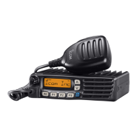
| Frequency Range | 136-174 MHz |
|---|---|
| Channel Spacing | 12.5/25 kHz |
| Mode | FM |
| Waterproof | IP54 |
| Type | Mobile Transceiver |
| Channel Capacity | 128 Channels |
General safety warnings regarding power and environment.
Guidelines for disassembling and servicing the transceiver safely.
Identifies components on the front unit PCB.
Identifies components on the top side of the main unit PCB.
Identifies components on the bottom side of the main unit PCB.
Describes RF, 1st IF, and 2nd IF/Demodulator signal paths.
Details the audio frequency signal path and amplification.
Describes tone signal extraction for decoding functions.
Describes the transmitter's signal path from mic to antenna.
Explains VCOs and PLL operation for frequency control.
Shows voltage distribution across the unit components.
Lists pin assignments for key ICs and their functions.
Lists required equipment and setup for adjustments.
Details frequency calibration steps and values.
Details transmit calibration steps like power and deviation.
Details receive calibration steps like sensitivity and squelch.
Lists mechanical parts for the chassis assembly.
Lists accessories and their associated parts.
Lists mechanical parts specific to the front unit.
Lists mechanical parts specific to the main unit.
Shows the top view of the main unit PCB with component locations.
Shows the top view of the front unit PCB with component locations.
Shows the bottom view of the main unit PCB with component locations.
Shows the bottom view of the front unit PCB with component locations.
Voltage diagram for the front unit's circuitry.
Voltage diagram for the main unit, part 1 of 2.
Voltage diagram for the main unit, part 2 of 2.