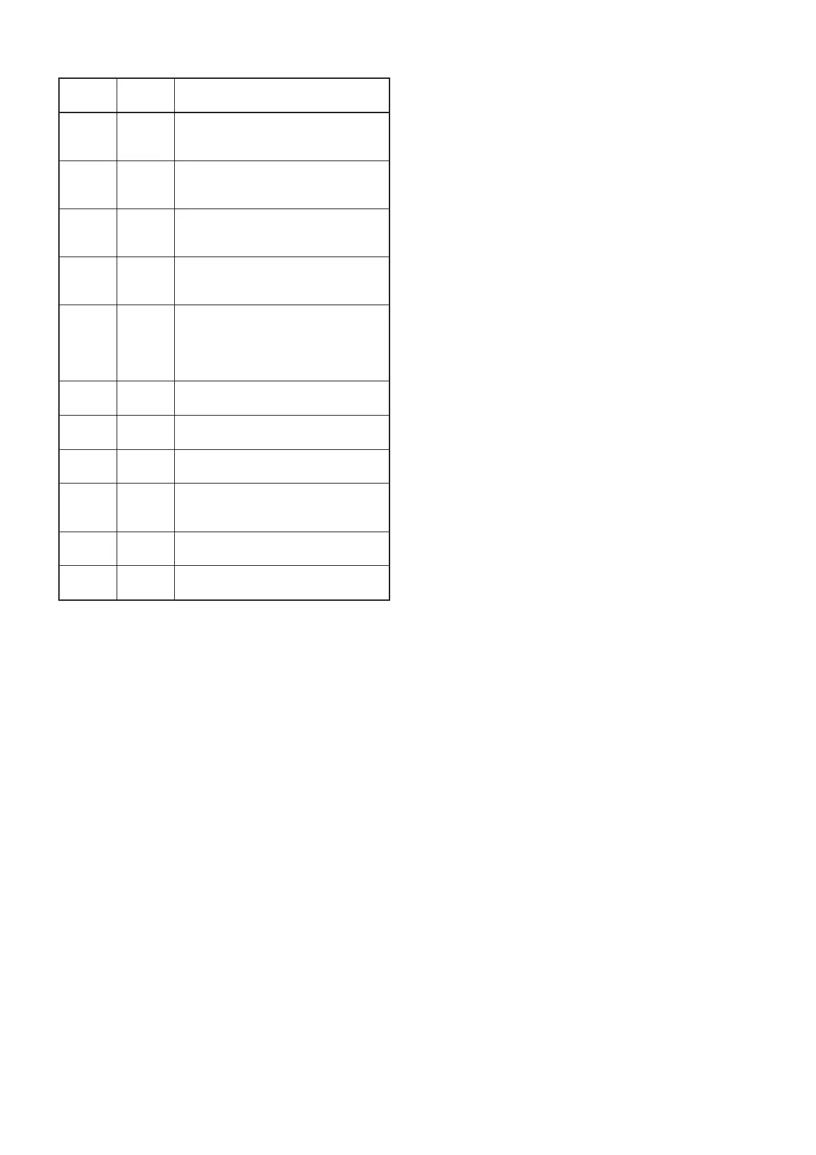
4 - 7
Pin
number
Port
name
Description
76 XTXD
Input port for the MAP27 data signals
from the connected unit via the exter-
nal connector (J9).
77 XRXD
Outputs the MAP27 data signals for
the connected unit via the external
connector (J9).
79 NTXD
Outputs the NMEA data signals for
the connected unit via external con-
nector (J8).
80 NRXD
Input port for the NMEA data signals
from the connected unit via external
connector (J8).
88 DIM
Input port for the LCD backlight con-
trol signal from the external connector
(J6).
Low: While LCD backlight is
dimmed.
89–91
CENC1–
CENC3
Output the CTCSS/DTCS signals.
92 AFCL
Outputs reset signal for the compand-
er IC (IC14).
96 APST
Outputs strobe signal to the com-
pander IC (IC14).
97 PMFM
Outputs the control signal for the MSK
PM/FM switch circuit (IC15).
Low: While PM is selected.
98 ESDA
I/O port for data signals from/to the
EEPROM (IC23).
99 ESCL
Outputs clock signal to the EEPROM
(IC23).