6 - 4
ADJUSTMENT
TRANSCEIVER’S
CONDITION
OPERATION
ADJUSTMENT
ITEM
VALUE
PLL LOCK
VOLTAGE
(RX)
1 • Channel : 1-1
• Receiving
1) Connect an RF power meter to the an-
tenna connector.
2) Set the adjustment value on the "Adjust
Utility" screen.
[RX LVA(Adjust)] 1.10 V
(TX) 2 • Channel : 1-2
• Transmitting
[TX LVA(Adjust)]
1.06 V
(RX)
[Verify]
3 • Channel : 1-3
• Receiving
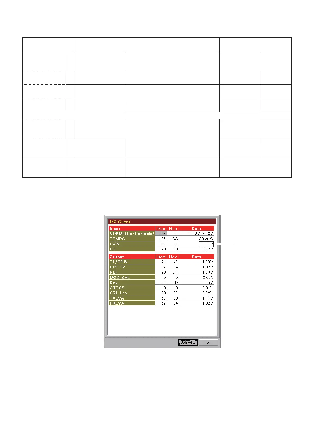
• Click the [Update (F5)] button to check on
the "I/O Check window" as below.
[LV (RX)]
3.0–4.0 V
(TX)
[Verify]
4 • Channel : 1-4
• Transmitting
[LV (TX)]
2.5–3.5 V
NOTE: Only when the lock voltage is not in the specifi ed range, perform following adjustments.
(RX) 5 • Channel : 1-3
• Receiving
1) Connect an RF power meter to the an-
tenna connector.
2) Set the adjustment value on the "Adjust
Utility" screen.
[RX LVA(Adjust)] 3.50 V
(TX) 6 • Channel : 1-4
• Transmitting
[TX LVA(Adjust)]
3.00 V
REFERENCE
FREQUENCY
1 • Channel : 1-5
• Transmitting
• Loosely couple a frequency counter to the
antenna connector.
[REF]
174.000000
MHz
(±50 Hz)
6-2 FREQUENCY ADJUSTMENTS
1) Select an adjustment item using [
↑
]/[
↓
] on the PC's keyboard.
2) Set or modify the adjustment value as specifi ed using [
←
]/[
→
] on the PC's keyboard, then push [ENTER].
(The values shown above are exsample only.
Each transceiver has own values.)
Lock voltage
appears here
* * *
• I/O Check screen
 Loading...