■ Optional UT-108 installation
Install the optional UT-108 unit as follows:
q Turn power OFF, then disconnect the DC power cable.
w Unscrew the 4 screws, then remove the bottom cover.
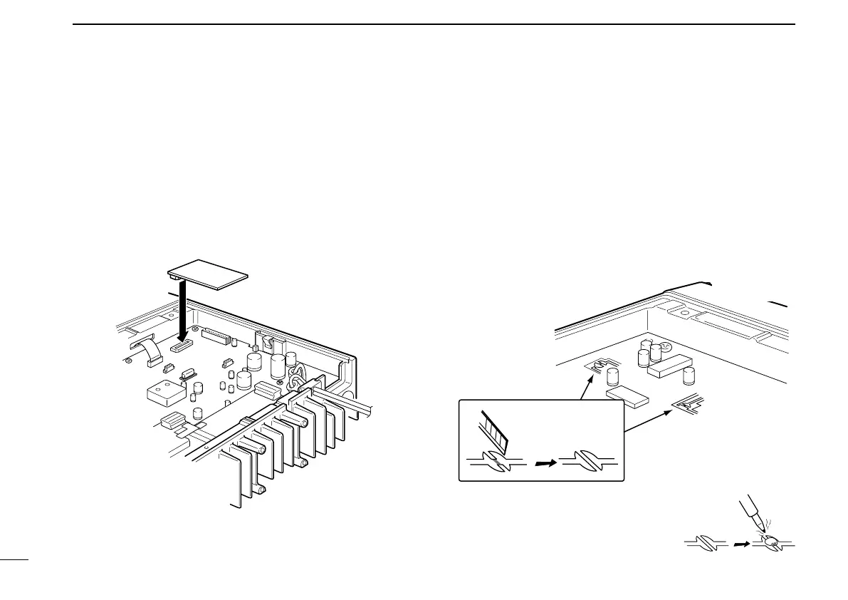
e Install the unit as shown in the diagram below.
r Replace the bottom cover and screws, then the DC
power cable.
■ Optional UT-109/UT-110
installation
q Turn power OFF, then disconnect the DC power cable.
w Unscrew the 4 screws, then remove the bottom cover.
e Cut the print pattern on the PCB at the TX mic circuit (A)
and RX AF circuit (B) as shown in the following figure.
r Install the scrambler unit as shown in the left.
t Return the bottom cover and screws to the original posi-
tion.
NOTE: Be sure to re-solder above
disconnected points, otherwise no TX
modulation or AF output is available
when you remove the scrambler units.
15
3
CONNECTION AND MAINTENANCE