4-1-5 Function Display
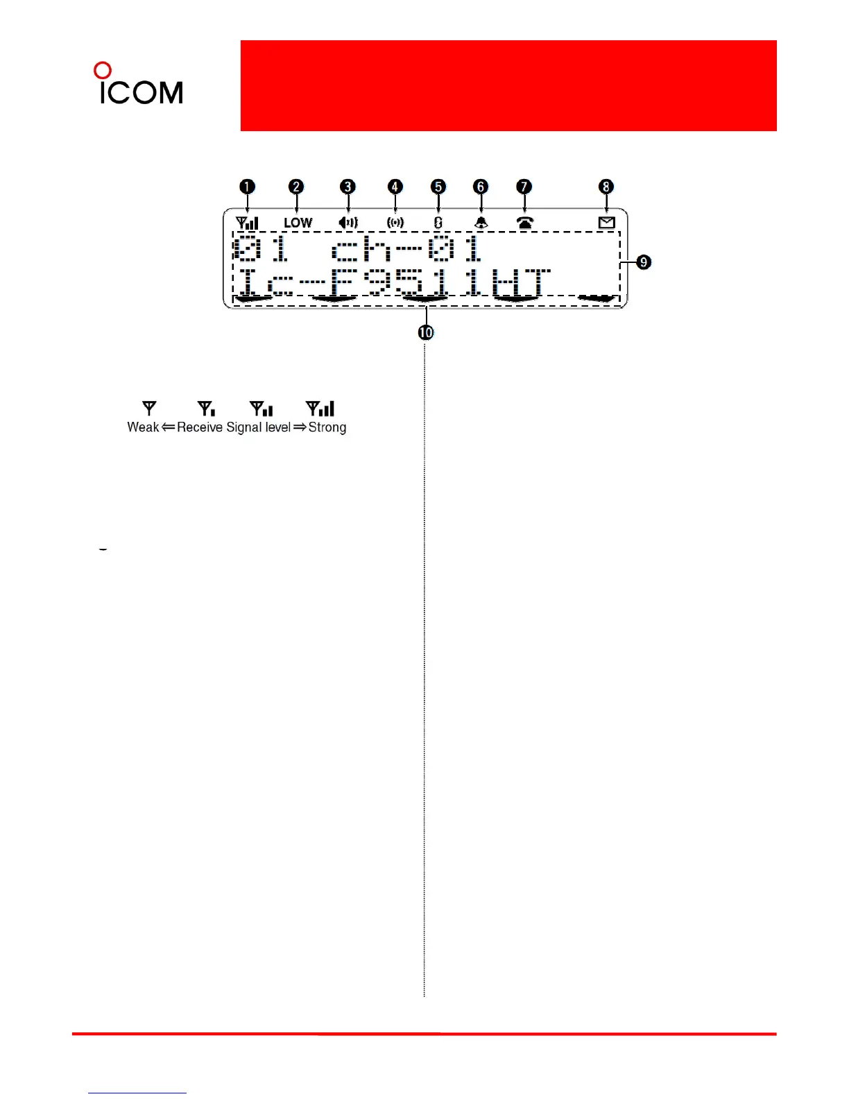
IC-F9511HT
➊RECEIVED SIGNAL STRENGTH INDICATOR
Indicates relative signal strength level.
➒ALPHANUMERIC DISPLAY
Displays an operating channel number, channel
name, Set mode contents, DTMF code, etc.
➋LOW POWER INDICATOR
Appears when low output power is selected.
* When high output power is selected, no
indicator appears.
AUDIBLE INDICATOR
➓ACTIVATED KEY INDICATOR
Appears above the key assigned as [Scan Add/Del
(Tag)] key when that key has been activated.
See the operating guide for details of Analog
and P25 Trunking/Conventional system
operations. Consult your Icom dealer or system
operator for details concerning your
Appears when the channel is in the ‘audible’
(unmute) condition.
➍COMPANDER INDICATOR
Appears when the compander function* is activated.
* Analog mode operation only
operator for details concerning your
transceiver’s programming.
Appears when the voice scrambler or encryption
function is activated.
➏BELL INDICATOR
Appears/blinks when the specific page call* is
received, depending on how the transceiver has been
pre-programmed.
y
➐TELEPHONE INDICATOR
Appears when a phone call* is received.
* P25 operation only
➑SHORT MESSAGE INDICATOR
Appears when a Status message or Short message is
31
received.
* P25 operation only
 Loading...