Do you have a question about the Icom IC-F24 and is the answer not in the manual?
General specifications including frequency coverage, emission type, and operating conditions.
Top and bottom views of the main circuit board with component identification.
Step-by-step guide to detach the chassis unit from the transceiver.
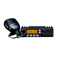
Procedures for removing the main unit for IC-F24/F25 models.
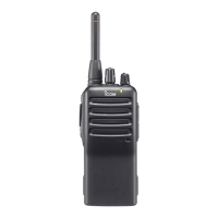
Procedures for removing the main unit for IC-F24S/F25S models.
Detailed description of the receiver signal path and components.
Required test equipment and system requirements for adjustments.
Steps to connect and begin software-based transceiver adjustments.
List of components for the main unit.
List of external cabinet components and accessories.
List of mechanical parts within the main unit.
List of mechanical parts for the chassis.
List of mechanical parts for the antenna unit.
List of mechanical parts for the connect unit.
Diagrams and identifiers for transistors and FETs.
Diagrams and identifiers for diodes.
Top view of the main PCB with component placement.
Top view of the antenna PCB with component placement.
Top view of the connect PCB with component placement.
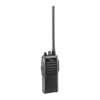
| Type | Handheld Transceiver |
|---|---|
| Frequency Range | 136-174 MHz |
| Channels | 16 |
| Power Output | 5W |
| Battery Life | Up to 12 hours |
| Channel Spacing | 12.5/25 kHz |
| Mode | FM |
| RF Power Output | 5W |
| Operating Voltage | 7.2 V |
| Voltage | 7.2 V |