Home
Icom
Transceiver
IC-F210S
Icom IC-F210S - User Manual
20 pages
Manual
Specs
Ask a question
Save Page as PDF
To Next Page
To Next Page
Loading...
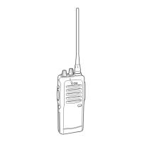
iF110S
VHF TRANSCEIVER
INSTRUCTION MANUAL
iF210S
UHF TRANSCEIVER
IC-F110_210S_GEN-1.qxd 05.9.16 9:46 AM Page a (1,1)
2
Table of Contents
Main Page
Important
2
Explicit Definitions
2
Cautions
2
Table of Contents
3
Panel Description
4
I Front Panel
4
I Function LED
5
I Programmable Function Keys
6
Panel Description
8
I Channel Selection
9
I Turning Power on
9
Operation
9
I Receiving and Transmitting
10
D Transmitting Notes
10
D Scrambler Function
11
Operation
11
D User Set Mode
11
Connection and Maintenance
12
I Rear Panel and Connection
12
I Supplied Accessories
13
I Mounting the Transceiver
14
I Optional UT-108 Installation
14
I Optional UT-109/UT-110 Installation
15
I Optional OPC-617 Installation
15
I Antenna
16
Connection and Maintenance
16
I Fuse Replacement
16
I Cleaning
16
Options
17
Need help?
Do you have a question about the Icom IC-F210S and is the answer not in the manual?
Ask a question
Icom IC-F210S Specifications
Print Specification
General
Frequency Range
136-174 MHz
Number of Channels
16
Channel Spacing
12.5/25 kHz
Mode
FM
IP Rating
IP54
Power Supply/Operating Voltage
13.8 V DC
Related product manuals
Icom IC-F210
38 pages
Icom IC-F2100D Series
50 pages
Icom IC-F21
38 pages
Icom IC-F211
24 pages
Icom IC-F21S
14 pages
Icom IC-F21GM
32 pages
Icom IC-F24
32 pages
Icom IC-F221
24 pages
Icom IC-F2000
46 pages
Icom IC-F25SR
48 pages
Icom IC-F2721
36 pages
Icom IC-F2000 series
26 pages