Do you have a question about the Icom IC-F21 and is the answer not in the manual?
Essential safety precautions for operating and handling the transceiver.
Guidelines for ordering replacement components, specifying necessary details.
Covers frequency coverage, emission type, power supply, dimensions, and environmental limits.
Details performance metrics for both transmitting and receiving functions.
Identifies key electronic components on the Main Unit's top and bottom views.
Step-by-step procedures for disassembling the transceiver's chassis and main unit.
Details the antenna switching, RF amplifier, IF stages, and AF circuits for signal reception.
Explains the microphone amplifier, modulation, and power amplifier stages for transmission.
Describes the Phase-Locked Loop, Voltage Controlled Oscillator, and power supply voltage distribution.
Covers the CPU functions and the allocation of its input/output ports.
Lists required equipment, software, and system setup for calibration procedures.
Illustrates how to connect various test instruments for transceiver adjustments.
Details the procedure for adjusting and verifying PLL lock voltage for RX and TX operations.
Covers setting reference frequency, RF output power, and FM deviation.
Details procedures for adjusting receiver sensitivity and squelch level.
Comprehensive list of all components for the main transceiver unit.
Lists components for SW-A, SW-B units, and accessories like battery packs.
Lists mechanical parts for chassis, main unit, and accessories, with visual aids.
Illustrates standard schematic symbols for transistors, FETs, and diodes used in the circuit.
Visual representation of component placement on the Main Unit's PCBs.
Visual representation of component placement on the SW-A and SW-B unit PCBs.
Details components and disassembly steps for the optional BC-146 desktop charger.
Provides voltage diagrams and PCB layouts for the BC-146 desktop charger.
A high-level overview of the transceiver's functional blocks and signal paths.
Illustrates voltage levels at critical points within the main transceiver unit.
Depicts voltage levels and signal paths for the SW-A and SW-B sub-units.
| Frequency Range | 136-174 MHz |
|---|---|
| Channel Capacity | 16 |
| Power Output | 5W |
| Mode | FM |
| IP Rating | IP54 |
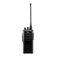
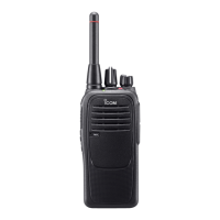
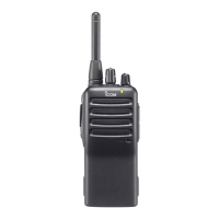
| Type | Handheld |
| Weight | 350g (with battery) |
| Battery Life | 10 hours |