EasyManua.ls Logo

Icom IC-F210 Service Manual

Icom IC-F210
38 pages
To Next Page IconTo Next Page
Page #1 background imageLoading...
Page #1 background image
UHF TRANSCEIVER
iF210
iF211
iF221
SERVICE
MANUAL

Other manuals for Icom IC-F210

Question and Answer IconNeed help?

Do you have a question about the Icom IC-F210 and is the answer not in the manual?

Icom IC-F210 Specifications

General IconGeneral
Frequency Range136-174 MHz
Power Output25W
Dimensions160 x 55 x 150 mm
Weight1.4 kg
Channel Spacing12.5/25 kHz
ModeFM
RF Power Output25W
Power Supply Requirement13.8 V DC
Voltage13.8 V DC

Summary

Introduction and Warnings

Critical Safety Warnings

Lists essential safety precautions for operation.

Parts Ordering and Repair Notes

Section 1 Specifications

General Specifications

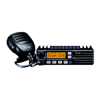
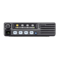
Covers overall device characteristics.

Transmitter Specifications

Details RF output, modulation, and emission parameters.

Receiver Specifications

Outlines sensitivity, selectivity, and audio performance.

Section 3 Disassembly Instructions

Section 4 Circuit Description

Receiver Circuitry

Explains the signal path for receiving.

Section 4 Circuit Description - Transmitter and Mute

Transmitter Circuits

Details the signal path for transmitting.

Section 4 Circuit Description - Power, PLL, VCO

Power Amplifier and APC Circuits

Covers output power amplification and protection.

PLL and VCO Circuits

Explains frequency generation and control.

Section 4-5 Port Allocations

Section 4-5 Port Allocations - Other Units

Section 5 Adjustment Procedures

Preparation and Software Setup

Outlines system requirements and software installation.

Required Test Equipment

5-2 PLL Adjustment

5-3 Software Adjustment

Core Software Adjustments

Covers frequency, power, deviation, and balance settings.

5-3 Software Adjustment - Sensitivity/Squelch

Sensitivity and Squelch Adjustments

Details adjustments for receiver sensitivity and squelch.

Section 9 Board Layouts

Section 9 Board Layouts - Front Unit Bottom View

Section 9-2 Main Unit Board Layout

Section 9-2 Main Unit Board Layout - Bottom View

Section 10 Block Diagram

Section 11 Voltage Diagrams

Section 11 Voltage Diagrams - Main Unit