3 - 1
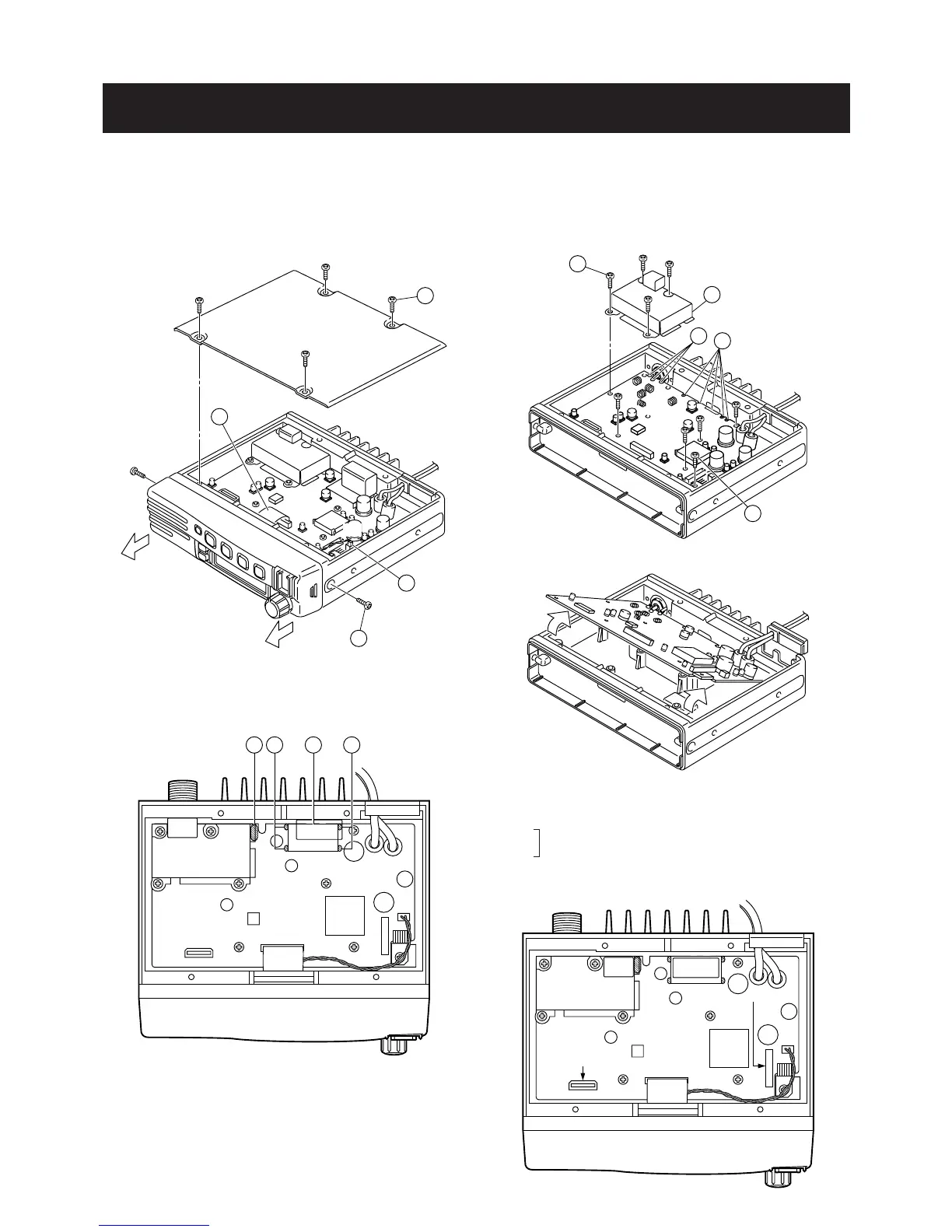
SECTION 3 DISASSEMBLY INSTRUCTIONS
• Opening case and removing the front unit
q Unscrew 4 screws A, and remove the bottom cover.
w Disconnect the flat cable B from J2.
e Disconnect the cable C from J7.
r Unscrew 2 screws D, and remove the front unit.
u Unscrew 8 screws H.
i Remove the filter case I.
o Unscrew the screw J.
!0 Unsolder 3 points K from the antenna connector.
!1 Unsolder 4 points L from IC3.
!2 Lift up the front portion of the main unit and remove it.
OPC-617
J1
J6
UT-105
UT-108
UT-109
UT-110
UT-111
t Unsolder 4 points E, and remove the plate F.
y Unsolder the point G.
• Installation location
UT-105 SmarTrank 2 logic board
UT-108 DTMF decoder unit
UT-109
Voice scrambler unit
UT-110
UT-111 Trunking unit
OPC-617 ACC cable (for external terminal connection)
 Loading...