Outputs dimmer control signal.
High: Dimmter is ON.
Outputs backlight control signal.
High: Backlight is ON.
Output LCD segment signals.
Output LCD common signals.
4 - 5
I/O ports for the optional board control
signals.
Input port for the clock sigal from the
optional board via J1.
Input port for the cloning signal.
Output port for the cloning signal.
Input port for the POWER switch.
• Input port for the remote power con-
trol signal from the external connec-
tor.(J6)
• Input port for the dimmer control.
Input port for the “NOIS” signal from
the FM IF IC (MAIN unit; IC1) for noise
squelch operation.
Input port for interruption signal from
the optional board via J1.
Outputs chip select signal for the
optional board via J1.
Input port for the PTT switch from
microphone.
Input port for the PTT switch from the
external connector (J6).
Low : External PTT switch is ON.
Input port for the microphone hanger
detection signal.
Low : Microphone on hook.
Input port for the AF volume control
signal (R14).
High : [VOL] is maximum clockwise.
Input port for the CTCSS/DTCS decod-
ing signals.
Input port for the single tone decoding
signal.
Input port for the optional board detec-
tion signal.
Input port for receiving signal strength
level detection.
Input port for the PLL lock voltage.
44–46
48
49
50
51
52
83
54
55
56
57
58
59
60
61
62
63
64
OPT3–
OPT1
SI
CLI
CLO
POSW
IGSW
NOIS
CIRQ
CCS
PTT
EPTT
HANG
AFVI
CDEC
SDEC
OPV1V2
RSSI
LVIN
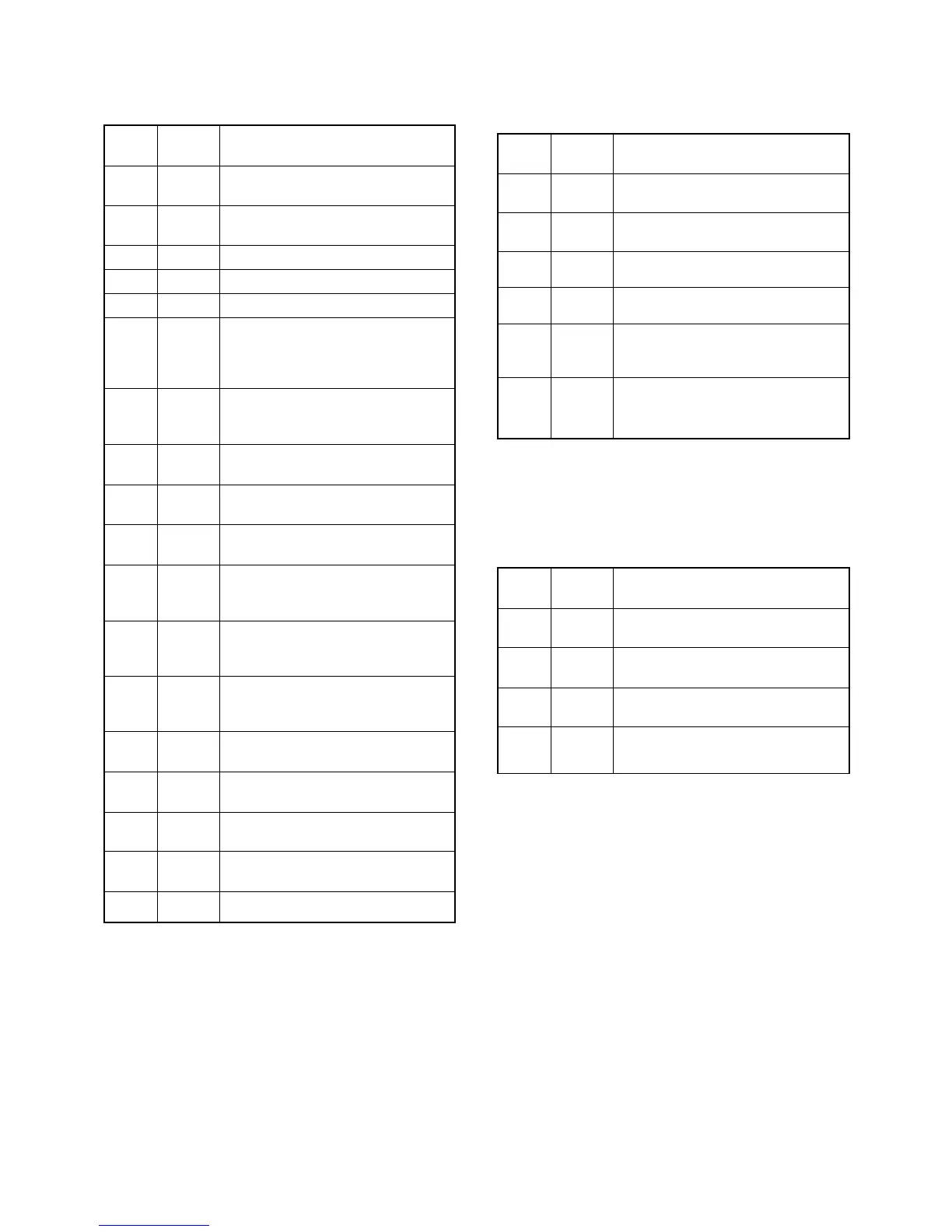
Pin Port
Description
number name
Outputs transmit/receive control signal.
High: While receiving.
Outputs audio output control signal.
High: While receiving.
Outputs wide/narrow control signal.
High: Wide is selected.
Outputs receiving mute control signal.
Low: While receiving is muting.
Outputs transmitting mute control sig-
nal.
Low: While transmitting is muting.
Outputs the microphone mute control
signal.
Low: While the microphone is muting.
4
5
6
7
13
14
RXC
AFON
NWC
RMUT
TMUT
MMUT
Pin Port
Description
number name
1
2
3–34
35–38
LIGT1
LIGT2
SEG32–
SEG1
COM4–
COM1
Pin Port
Description
number name
4-5-3 LCD DRIVER (FRONT UNIT; IC6)
4-5-2 OUTPUT EXPANDER (MAIN UNIT; IC17)CPU-Continued
 Loading...