Do you have a question about the Icom IC-H6 and is the answer not in the manual?
General specifications including semiconductor count, channels, stability, temperature range, and impedance.
Receiver specifications including frequency range, sensitivity, IF, squelch, and audio output.
Transmitter specifications including frequency range, output power, emission mode, and deviation.
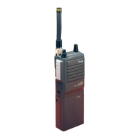
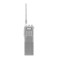
Identifies controls located on the top panel of the transceiver.
Identifies controls located on the front and rear panels of the transceiver.
Detailed explanations for each numbered control on the transceiver.
Explains the receiver's antenna switching, RF amplifier, mixer, and IF circuits.
Details the transmitter's mic amplifier, multiplier, driver, and power amplifier circuits.
Describes Phase-Locked Loop circuits including oscillator and divider.
Covers reference frequency, phase detector, loop filter, VCO, and power supply circuits.
Visual representation of the transceiver's circuit blocks and signal flow.
Labeled diagram showing components within the main unit.
Labeled diagram showing components within the PLL unit.
Step-by-step instructions for removing the transceiver's outer cases.
Instructions for disassembling internal units like the rear panel and matrix board.
Procedure for replacing the Push-to-Talk (PTT) spring.
Exploded view and parts list for the top panel assembly.
Instructions for disassembling and replacing the contact spring on the unit's bottom.
Lists necessary test equipment for maintenance and adjustment procedures.
Initial checks for transmitter output and receiver functionality before servicing.
Steps for confirming issues and preparing for repair and adjustment.
Procedures for checking receive, transmit, and modulation functions.
Step-by-step guide for aligning the PLL circuit, transmitter, and receiver.
Top-down view of the main unit's PCB with component placement.
Top-down view of the PLL unit's PCB with component placement.
Layout diagram of the matrix unit showing channel programming connections.
Table of DC voltage readings for transistors in transmit/receive modes.
Table of DC voltage readings for ICs in transmit/receive modes.
Detailed schematic of the main unit's electronic circuits.
Detailed schematic of the PLL unit's electronic circuits.
Flowchart to diagnose and resolve issues when the unit does not power on.
Flowchart to diagnose and resolve PLL lock failure issues.
Flowchart to diagnose and resolve issues when the unit does not receive signals.
Flowchart to diagnose and resolve issues with no transmit RF power.
Specs, pin connection, and block diagram for the TC-9122P IC.
Specs, pin connection, and block diagram for the MC-3357 IC.
Specs and pin connections for TC-5081, TC-5082, and BA-526 ICs.
List of parts used in the main unit of the transceiver.
List of parts used in the PLL unit of the transceiver.
List of parts used in the matrix unit of the transceiver.
Complete schematic of the IC-H6 transceiver, showing all circuit connections.
| Frequency Range | 136-174 MHz |
|---|---|
| Mode | FM |
| Receiver Sensitivity | 0.25 μV (12 dB SINAD) |
| Waterproof | IP67 |
| Power Output | 5.5W |