7-
5
BASIC
ALIGNMENT PROCEDURE
7-5-1
P.L.L. CIRCUIT
A.
Lock
Adjustment
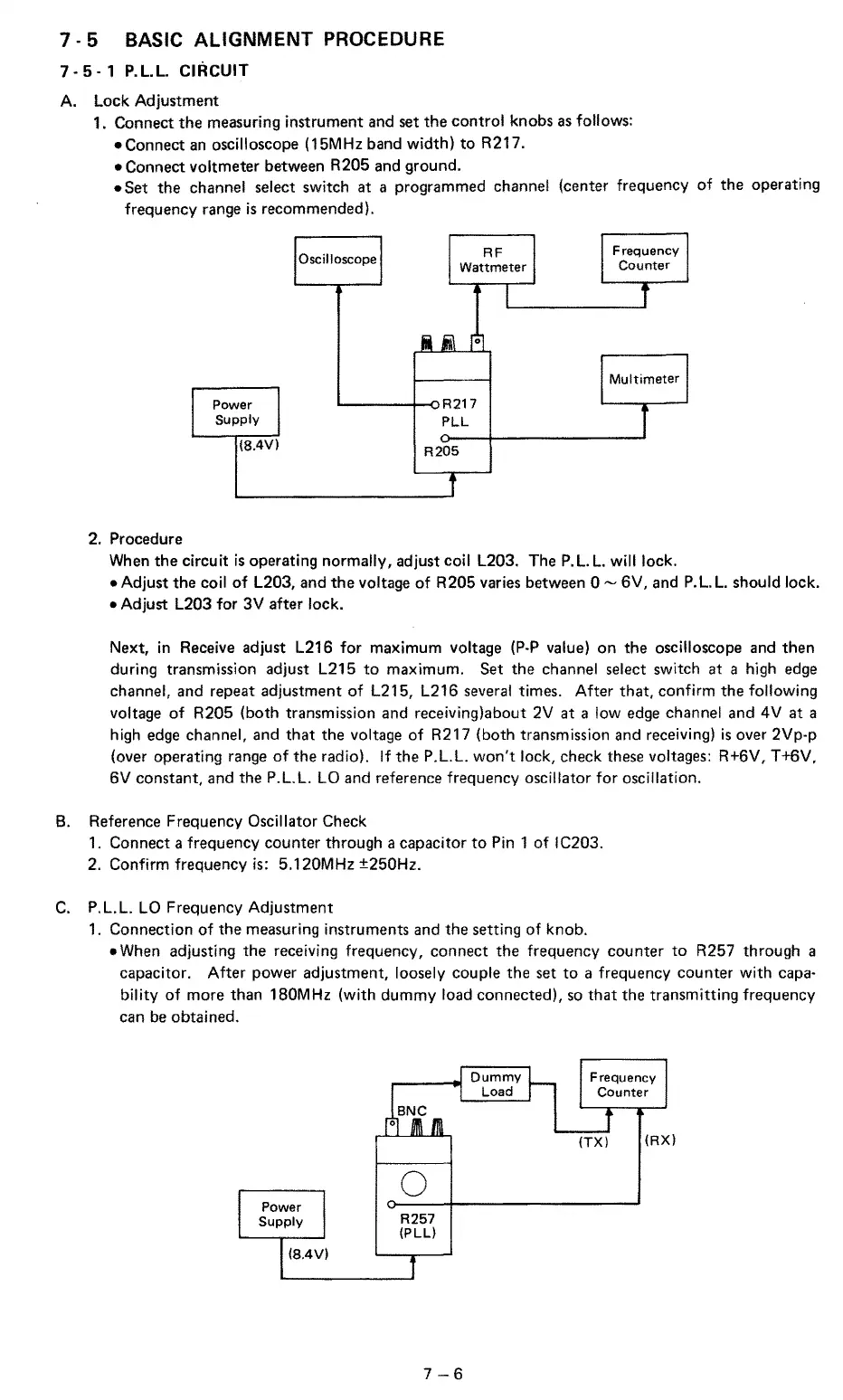
1.
Connect the measuring instrument and
set
the
control
knobs
as
follows:
•Connect
an
oscilloscope (15MHz band
width)
to
R217.
•Connect
voltmeter between R205
and
ground.
•Set
the channel select switch at a programmed channel (center frequency
of
the operating
frequency
range
is
recommended).
2. Procedure
Power
Supply
(8.4Vl
Oscilloscope
RF
Wattmeter
'------+--o
R21
7
PLL
R205
Frequency
Counter
When the
circuit
is
operating normally, adjust coil L203. The
P.
L.
L.
will
lock.
•Adjust
the coil
of
L203, and
the
voltage
of
R205 varies between 0
~
6V,
and
P.
L. L.
should lock.
•Adjust
L203
for
3V
after lock.
Next, in Receive adjust L216
for
maximum voltage
(P-P
value) on the oscilloscope and then
during transmission adjust
L215
to
maximum. Set the channel select switch at a high
edge
channel, and repeat adjustment
of
L215,
L216
several
times.
After
that,
confirm
the
following
voltage
of
R205 (both transmission and receiving)about
2V
at
a
low
edge
channel and
4V
at
a
high
edge
channel, and
that
the voltage
of
R217 (both transmission and receiving)
is
over 2Vp-p
(over operating
range
of
the radio).
If
the P.L.L.
won't
lock, check
these
voltages: R+6V, T+6V,
6V
constant, and the P.L.L. LO and reference frequency oscillator
for
oscillation.
8. Reference Frequency Oscillator Check
1.
Connect a frequency counter through a capacitor
to
Pin 1
of
IC203.
2. Confirm frequency is: 5.120MHz ±250Hz.
C.
P.L.L. LO Frequency Adjustment
1.
Connection
of
the measuring instruments and the setting
of
knob.
•When
adjusting the receiving frequency, connect the frequency counter
to
R257 through a
capacitor.
After
power adjustment, loosely couple the
set
to
a frequency counter
with
capa·
bility
of
more than 180MHz
(with
dummy
load connected),
so
that
the transmitting frequency
can
be
obtained.
Power
Supply
(8.4V)
___
..
Dummy
Load
0
R257
(PLL)
7-6
Frequency
Counter
(TX)
(RX)