37
7
INSTALLATION AND CONNECTIONS
New2001
1
2
3
4
5
6
7
8
9
10
11
12
13
14
15
16
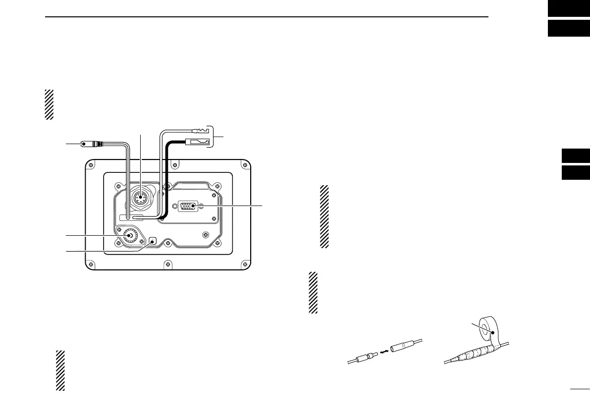
■ Connections
About the installation distance from the compass:
KEEP the transponder at least 1 m (3.3 ft) away from the
vessel’s magnetic navigation compass.
q CLONING CABLE CONNECTOR
Connects the cloning cable from this connector to a PC.
Ask your dealer for details.
w INTERNAL GPS RECEIVER CONNECTOR
Connects to the MXG-5000 to receive position data and
transmit it with other AIS information.
NOTE: Important notes and how to install the MXG-
5000 are described on the instruction sheet that comes
with it. Be sure to read them before installing and oper-
ating the MXG-5000.
e DC POWER CONNECTOR
Connects the supplied DC power cable between this con-
nector and a 12 V power source.
r HIGH-DENSITY D-SUB 15 PIN (NMEA IN/OUT)
Connects an Icom MarineCommander™ system, naviga-
tion equipment, external GPS receiver, etc. using the sup-
plied OPC-2014
n m e a c o n n e c t o r c a b l e .
See page 39 for the pin assignment.
Requirements of the external GPS:
• The datum of the external GPS receiver must be
“WGS-84.”
• GBS sentence can be input using the RAIM function.
• The external GPS antenna must be installed within
26 m (85.3 ft) of the internal GPS antenna.
CAUTION: After connecting the DC power cable and
NMEA connector cable leads, cover the cable and leads
with a rubber vulcanizing tape, to prevent water seeping
into the transponder.
 Loading...