Do you have a question about the Icom MA-510TR and is the answer not in the manual?
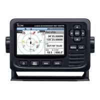
Lists key features of the MA-510TR transponder, including display, connectivity, and interface.
Explains the meaning of warning symbols like WARNING!, CAUTION, and NOTE used in the manual.
Provides instructions for cleaning the transponder with fresh water after saltwater exposure to prevent salt crystallization.
Details installation requirements regarding electromagnetic field exposure limits and antenna placement.
Declares compliance with EU directives, providing an internet address for the declaration.
Instructs on the proper disposal of the product and its batteries according to EU regulations.
Emphasizes FCC requirements for radio frequency exposure and specifies safe antenna mounting distances for personnel.
Lists critical warnings and cautions for connecting power, handling the device, and operating during storms.
Provides temperature limits and waterproof protection notes for the GPS antenna.
Explains the Automatic Identification System's purpose for collision risk management and navigation safety.
Describes the 7 types of AIS stations and the 2 classes of AIS units (Class A and Class B).
Details the function and operation of each button and key on the transponder's front panel.
Explains the meaning of various icons displayed on the transponder's screen, such as TX OFF, GPS, and Message icons.
Guides the user through the one-time process of entering the Maritime Mobile Service Identity (MMSI) code.
Explains how to input essential vessel information like ship name, call sign, and ship type for AIS transmission.
Details specific fields for vessel information including MMSI, name, call sign, and ship type.
Illustrates the tree structure of the menu system and how to navigate through different settings and options.
Provides a step-by-step guide on how to select and change settings within the transponder's menu system.
Details the procedure for turning the transponder on, including self-check and GPS acquisition.
Explains how to adjust the display and key backlight for optimal visibility in different lighting conditions.
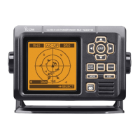
Describes the different main screen types and how to view AIS targets, waypoints, and GPS data.
Explains the components of the AIS screen, including display range, vessel icons, and target information.
Details the AIS and Steering screen, showing plotter display and steering information such as COG and bearing.
Describes the AIS and Highway screen, which displays highway information and navigation guidance.
Explains the Highway screen's display of navigation information including range, XTE, SOG, and COG.
Explains the content displayed in the information box for selected AIS targets or waypoints, varying by type.
Guides on how to view and manage AIS target lists, including target, danger, and friends lists.
Displays detected AIS targets and registered friends, sorted by distance or CPA/TCPA.
Shows dangerous targets sorted by CPA/TCPA, indicating proximity and time to collision.
Explains how to register AIS targets as friends to receive specific alarms and manage the friends list.
Details the procedure for removing an ID from the Friends list.
Details the information available on the detail screen for various AIS target types, including Class A, Class B, and Base stations.
Covers settings for TX function, display types (North up/Course up), and AIS target display limits.
Configures CPA/TCPA alarms, danger target lost alarms, and sets CPA and TCPA values.
Manages Slow Warn function for anchored vessels and ID blocking to suppress alarms from specific targets.
Explains how to receive, view, and manage safety-related messages transmitted between AIS vessels.
Covers creating, navigating to, editing, and deleting waypoints for navigation assistance.
Describes how to activate and deactivate the Man Overboard (MOB) function for emergency location tracking.
Details how to start, stop, and reset navigation to a selected destination or waypoint.
Explains the criteria and time intervals for identifying a vessel as a 'Lost target' based on its transmission status.
Guides on initiating an Individual DSC call to another vessel via the transponder when connected to a transceiver.
Lists AIS list types and configuration options for TX, display, and CPA/TCPA alarms.
Covers navigation settings like Waypoint, Track, and Friends list management with alarms.
Details NMEA data transfer settings and general device configuration options like backlight and language.
Explains how to view AIS information, RX log, status, and radio details like serial number.
Lists and illustrates the accessories supplied with the transponder, such as DC power cable and GPS antenna.
Provides instructions for installing and connecting the GPS antenna, along with notes on position calculation and accuracy.
Details the various connectors on the transponder, including VHF, NMEA, GPS, power, and data ports.
Provides a detailed pinout for the NMEA 0183 connector, specifying pin names, specifications, and sentence formats.
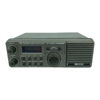
Explains how to connect the transponder to compatible VHF transceivers for DSC call functionality.
Details the process for replacing the fuse in the DC power cable if the transponder stops functioning.
Guides on how to mount the transponder using the supplied bracket, including placement away from compasses.
Describes the procedure for flush mounting the transponder using the optional MB-132 kit.
Lists detailed technical specifications for the transmitter, receiver (AIS and DSC), and GPS receiver.
Details the specifications for the GPS receiver, including frequency, acquisition, and satellite support.
Provides dimensional drawings and measurements for the MA-510TR unit and its mounting bracket.
Mentions optional accessories available for the transponder, such as flush mount kits.
Offers solutions for common problems like the transponder not turning on, not transmitting, or alarms not sounding.
Lists and explains various error messages that may appear on the transponder, indicating specific malfunctions.
Lists and describes the codes used for Aids to Navigation (AtoN) that may be displayed on the detail screens.
Provides a template for cutting holes or marking positions for flush mounting the transponder.
| Output Power | 2W |
|---|---|
| AIS Transponder | Yes |
| Waterproof Rating | IPX7 |
| Display | LCD |
| Operating Temperature Range | -15°C to +55°C |
| Modulation | GMSK |
| Type | Class B AIS Transponder |
| Frequency Range | 161.975 - 162.025 MHz |
| GPS | Yes |
| Power Supply | 10 - 32 V DC |
| Channels | AIS 1 (161.975 MHz), AIS 2 (162.025 MHz) |