39
7
INSTALLATION AND CONNECTIONS
New2001
1
2
3
4
5
6
7
8
9
10
11
12
13
14
15
16
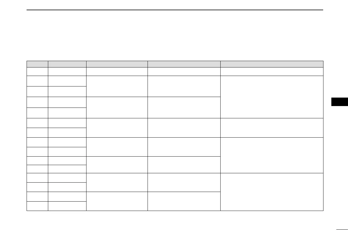
PIN No. PIN No. SPECIFICATIONS SENTENCE FORMAT DESCRIPTION
1 GND
— — Connects to ground.
2 NMEA1 OUT (–)
• Output level
: 5 V/40 mA max.
( RS-422 balanced type)
DSC, RMC, GGA, VTG, GSA,
GSV, GBS, DTM, DSE, GNS,
GLL
Connects to the NMEA input/output connector of
a transceiver to transmit an Individual DSC call,
or to connect to a GPS receiver. (p. 41)
The data communication speed (baud rate) can
be selected between 4800 bps (IEC61162-1) and
38400 bps (IEC61162-2) for each Input/Output
port.
(Default: 4800 bps)
3 NMEA1 OUT (+)
4 NMEA1 IN (–)
• Input level
: Less than 2 mA
(at 2 V applied)
RMC, GGA, VTG, GSA, GSV,
GBS
†
, DTM, GNS, GLL
5 NMEA1 IN (+)
6 ALERT1
• Load rating
: DC 24 V/500 mA max.
—
A short occurs between pins 6 and 11 when the alarm
buzzer sounds if a malfunction occurs, or an AIS
target is closer than your CPA and TCPA settings.
11 ALERT2
7 NMEA2 OUT (–)
Same as pins 2 and 3
VDM, VDO, ALR, ACA, ACS, TXT,
RMC*, GGA*, GNS*, GLL*, VTG*,
GSA*, GSV*, GBS*, DTM*
Connects to the Icom MarineCommander™ sys-
tem or to a GPS receiver.
The data communication speed (baud rate) is
fixed to
38400 bps
(IEC61162-2) for each Input/
Output port.
8 NMEA2 OUT (+)
9 NMEA2 IN (–)
Same as pins 4 and 5
RMC, GGA, VTG, GSA, GSV,
GBS
†
, DTM, GNS, GLL
10 NMEA2 IN (+)
12 NMEA3 OUT (–)
Same as pins 2 and 3
RMC, GGA, VTG, GSA, GSV,
GBS, DTM, GNS, GLL
Connects to a piece of navigation equipment or
to a GPS receiver.
The data communication speed (baud rate) can
be selected between 4800 bps (IEC61162-1) and
38400 bps (IEC61162-2) for each Input/Output
port.
(Default: 4800 bps)
13 NMEA3 OUT (+)
14 NMEA3 IN (–)
Same as pins 4 and 5
RMC, GGA, VTG, GSA, GSV,
GBS
†
, DTM, GNS, GLL
15 NMEA3 IN (+)
†
When a received GPS signal includes no GBS sentence, the transponder will not receive the signal from the external GPS receiver.
* Sent only when the “AIS+GPS” option is set in “AIS Output.” (p. 12)
New2001


 To Next Page