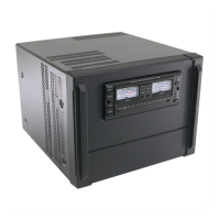
Care and Feeding an Icom PW1
W6DE
Copyright 2017, All rights reserved.
Regarding: My PW1 won't tune up on 6 meters even into a dummy load. All other bands will put out
1000 watts but not on 6 meters. Note: This is symptom can also apply to other bands not working.
To diagnose, on the Main Unit board at connector J8 measure the voltage for each band filter selection
as you manually go through each band. There is not a filter for each band, some bands are combined—
check the service manual. When engaged each the voltage for each band filter will be ~13 Volts.
You will likely find one of the band filter voltages to be significantly lower than the others. I don’t
remember exactly what it was, but it wasn’t zero. If you find filter select voltage too low, then you need
to repair two separate boards in the PW1!
Required Fix 1: Filter Unit, remove the filter unit. It is in the left front side of the chassis assembly. The
combiner assembly is attached to the filter and they will come out together. NOTE: the black two wire
(red and black wires inside a black casing) termination on the Combiner Board looks likes it is a
connector on the Combiner Board. That is NOT a connector attached to the Combiner board—it won’t
remove! After removal of the Filter/Combiner, separate the combiner from the filter assembly. Then
remove the circuit board from the filter assembly sheet metal.
Then (for 6 meters) replace diode D18. Other bands will have a corresponding diode across the relay
coil—see next paragraph.
You won’t find this diode in any standard catalog. It is a general purpose diode being used as a clamp
diode. I used a fast recovery diode P/N 1N5602. Mouser Electronics P/N 610-1N5062.
It is not always the 50MHz filter relay clamp diode that fails, other band relay clamp diodes fail. On
other band fail to select problems, there is a corresponding clamp diode for each band filter relay. The
failed bands have been indicated by reading the band filter select voltages on the Main Board connector
J8.
Note: it is likely you won’t be able to detect a failed clamp diode while it is in place on the circuit board.
Furthermore, this is a 50 cent device protecting a $300 board and it took you 2 to 3 hours to get to it—
just replace it. Be sure to observe polarity markings.
Required Fix 2: On the Main Unit, replace Integrated Circuit IC19. It is a Display driver used as a relay
driver. Toshiba P/N TD62783AFG(O,S,EL), Mouser Electronics part number 757-TD62783AFGOSEL.
Replacing the SMT driver chip is a delicate operation but doable using a CHIPQUIK SMD Removal Kit. Do
a Google search and watch a video or two.
However, if you don’t want to mess with the SMT chip removal you can buy, from ICOM Service Center
Parts, a 98415169 “Main Unit New Version circuit board”. As I recall it is in the $200 to $300 range.
“New Version” means it is for later versions of the PW1s that can still select bands with the PW1 power
off. It can probably be used to upgrade and repair your original PW1 too—I haven’t done this upgrade,
so you are on your own. CAUTION you still have to repair the appropriate blown Clamp diode on the
filter board or you are going to blow up the new board too!!!!!
For additional information on diagnosing and repairing PW1s; ZS6KR provides this excellent advice:
http://www.ab4oj.com/icom/pw1/zs6kr_pw1_repair.pdf

 Loading...