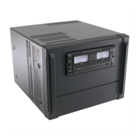
Care and Feeding an Icom PW1
W6DE
Copyright 2017, All rights reserved.
What causes PW1s to blow up?
I have found no inherent failure modes in the PW1. It is my opinion that some of the PW1’s protection
circuitry may not act fast enough for self-protection from some common operator errors.
PW1 amplifiers blow up because of these operator errors:
You use a computer to control your radio and PW1 without CI-V arbitration,
The ALC is set wrong,
The PW1 is set to the wrong band,
The PW1 is operated into the wrong antenna,
The PW1 is intentionally operated into a high SWR antenna,
Also, the PW1 ‘Antenna Tuner’ is operated at high power in an attempt to tune out a high SWR,
The operator forgot to turn off Split when he/she change bands,
The operator failed to disconnect the PW1 from the mains during a lightning storm.
Here are some details on operator errors that can cause your PW1 to FAIL.
One: CI-V control collisions:
This is the noted CI-V collision problem that leaves the PW1 on the wrong band. See: K8UT’s “Riding the
CI-V Bus” at:
http://www.k8ut.com/download/documents/Riding%20the%20CI-V%20Bus%20by%20K8UT.pdf
K8UT describes the problem and several cures. I use the k9jm solution.
If you have a computer, PW1 and Icom radio connected to each other, all on the CI-V buss, you are just
marking time until you have a PW1 failure. Icom specifically states in their documentation NOT TO DO
THIS. Please note: this is when will the failure occur not an IF the problem can occur! Yes, this means if
you have a (1) PW1, (2) an Icom radio and (3) a computer on the CI-V buss you are just waiting for the
problem to happen! This is how an “Automatic” system transmits into the wrong band or antenna!
HOWEVER, Icom has implemented a solution for this problem in the Icom 7850 and 7851 (that
have the latest Firmware installed) and it appears this fix is also in the IC-7610. These radios
have built in mitigation for the PW1 CI-V collisions and are thus PW1 friendly.
The basis of the 7850/7851 solution are two electrically separate CI-V data paths:, 1) a miniature
phono jack and 2) one of the USB ports on the radio’s back panel. The logical connection can be
separate or combined by menu software selection. If a PW1 connection is desired:
In the 7850/7851 Menu Option: CI-V USB Port, select Unlink [default is linked]. Then the
miniature phono jack (aka the Remote jack) on the rear panel can be connected to a PW1 and
the USB port on the rear panel can be connected to your computer for control. I.e., the “Unlink”
selection disconnects miniature phono from the computer control path, making possible a safe
PW1 control connection. And, a separate firmware section in the 7850/7851 keeps the PW1
informed of the radio’s status. Also, see the menu selection for: CI-V USB/LAN-> REMOTE
Transceive Address for additional instruction.

 Loading...