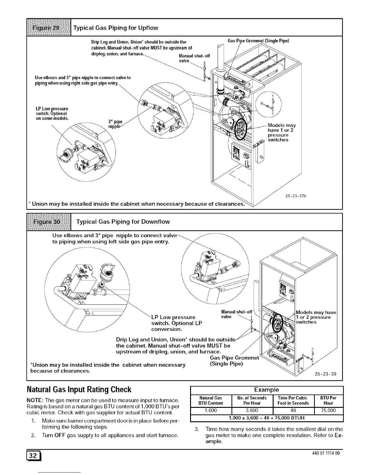
Typical Gas Piping for Upflow
Drip Leg and Union, Union* should be outside the Gas (Single Pipe)
cabinet. Manual shut-off valve MUSThe upstream of
dripleg, union, Manual shut- off
valve
Useelbows and3" pipenippleto connectvalveto
pipingwhenusingright sidegas pipe entry.
LP Lowpressure
switch. Optional
on some models.
nipp
* Union may be installed inside the cabinet when necessary because
25-23-37b
Typical Gas Piping for Downflow
Use elbows and 3" pipe nipple to connect valve's-
to piping when using left side gas pipe entry.
LP Low pressure
switch. Optional LP
conversion.
Manualshut- off
valve
Drip Leg and Union, Union* should
the cabinet. Manual shut-off valve MUST be
upstream of dripleg, union, and furnace.
Gas Pipe Grommet
*Union may be installed inside the cabinet when necessary (Single Pipe)
because of clearances.
25-23-39
Natural Gas Input Rating Check
NOTE: The gas meter can be used to measure input to furnace.
Rating is based on a natural gas BTU content of 1,000 BTU's per
cubic meter. Check with gas supplier for actual BTU content.
1. Make sure burner compartment door is in place before per-
forming the following steps.
2. Turn OFF gas supply to all appliances and start furnace.
Example
Natural Gas No.ofSeconds | Time PerCubic BTUPer
BTU Content PerHour _ Footin Seconds Hour1,000 3,600 48 75,000
1,000 x 3,600 + 48 = 75,000 BTUH
3. Time how many seconds it takes the smallest dial on the
gas meter to make one complete revolution. Refer to Ex-
ample.
[_ 440 01 111400