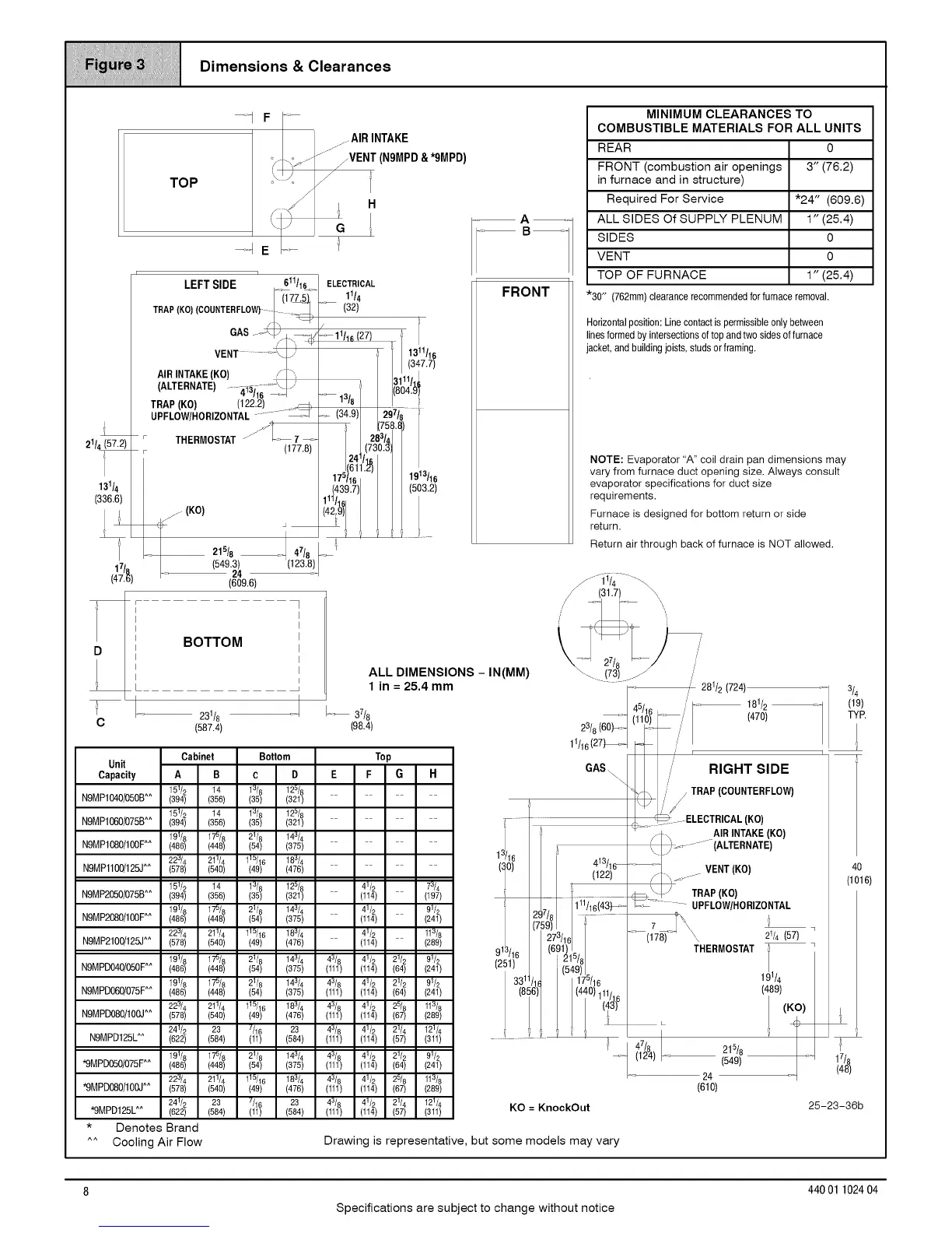
Dimensions & Clearances
--1 F
TO P "\-
/
-_ E
........ AIR INTAKE
_..z-Iz" fVENT (N9MPD & *9MPD)
'_ t H
21/_
]
LEFT SIDE ,611/1__
TRAP(KO)(COUNTERFLOW)_ _
GAS...
VENT ........_J.)
AIRINTAKE(KO) ,/_,,
(ALTERNATE) 4:1:_116"_J)
i
TRAP (KO) (122.2) _
UPFLOW/HORIZONTAL.............
• THERMOSTAT //'k __ 7 --_
(177.8)
215/8 I 47/8
(549.3) (123.8)
24
(609.6)
ELECTRICAL
11/4
(32)
13/B
(34.9)
175/16 1913/16
(439.7) (503.2)
111/16I
(42i9)
A
FRONT
MINIMUM CLEARANCES TO
COMBUSTIBLE MATERIALS FOR ALL UNITS
REAR 0
FRONT (combustion air openings 3" (76.2)
in furnace and in structure)
Required For Service *24" (609.6)
ALL SIDES Of SUPPLY PLENUM 1" (25.4)
SIDES 0
VENT 0
TOP OF FURNACE 1" (25.4)
*30" (762mm)dearancerecommendedforfurnaceremoval.
Horizontalposition:Linecontactispermissibleonlybetween
linesformedbyintersectionsoftopandtwosidesoffurnace
jacket,andbuildingjoists,studsorframing.
NOTE: Evaporator "A" coil drain pan dimensions may
vary from furnace duct opening size. Always consult
evaporator specifications for duct size
requirements.
Furnace is designed for bottom return or side
return.
Return air through back of furnace is NOT allowed,
(31.7)
BOTTOM
.... 231/8
C (587.4)
Cabinet
Unit
Capacity
N9MP1040/050B^^
N9MP1060/075B^^
N9MP1080/100F^^
N9MPl100/125J^^
N9MP2050/075B^^
N9MP2080/100F^^
N9MP2100/125J^^
N9MPD040/050F^^
N9MPD060/075F^^
N9MPD080/100J^^
N9MPD125L^^
*9MPD050/075F^^
*9MPD080/100J^^
*9MPD125L^^
* Denotes Brand
^^ Cooling Air Flow
_ 37/8
(98.4)
ALL DIMENSIONS - IN(MM)
1in=25,4mm
Bottom Top
23/8(60)_
11/16(27)_
GAS..
\
1110
(10) 413/16_
_, (122)
I r;I '/18 .........
27
91 /16 (6 I1)/
{2'I}3
175/16
(440)111,
/
/ 281/2 (724)
r
/' RIGHT SIDE
,' / TRAP(COUNTERFLOW)
ELECTRICAL(KO)
_- I AIR INTAKE (KO)
_. ).......... (ALTERNATE)
_J
_/t, ' VENT(KO)
_\]-) TRAP(KO)
C- UPFLOW/HORIZONTAL
(178) \ 21/4(57)
THERMOSTAT T
1
(489)
47/8 215/8
(124) - (549)
24
(610)
(KO)
3L
17/8
(48)
KO = KnockOut 25-23-36b
Drawing is representative, but some models may vary
8 44001 102404
Specifications are subject to change without notice