- 10 -
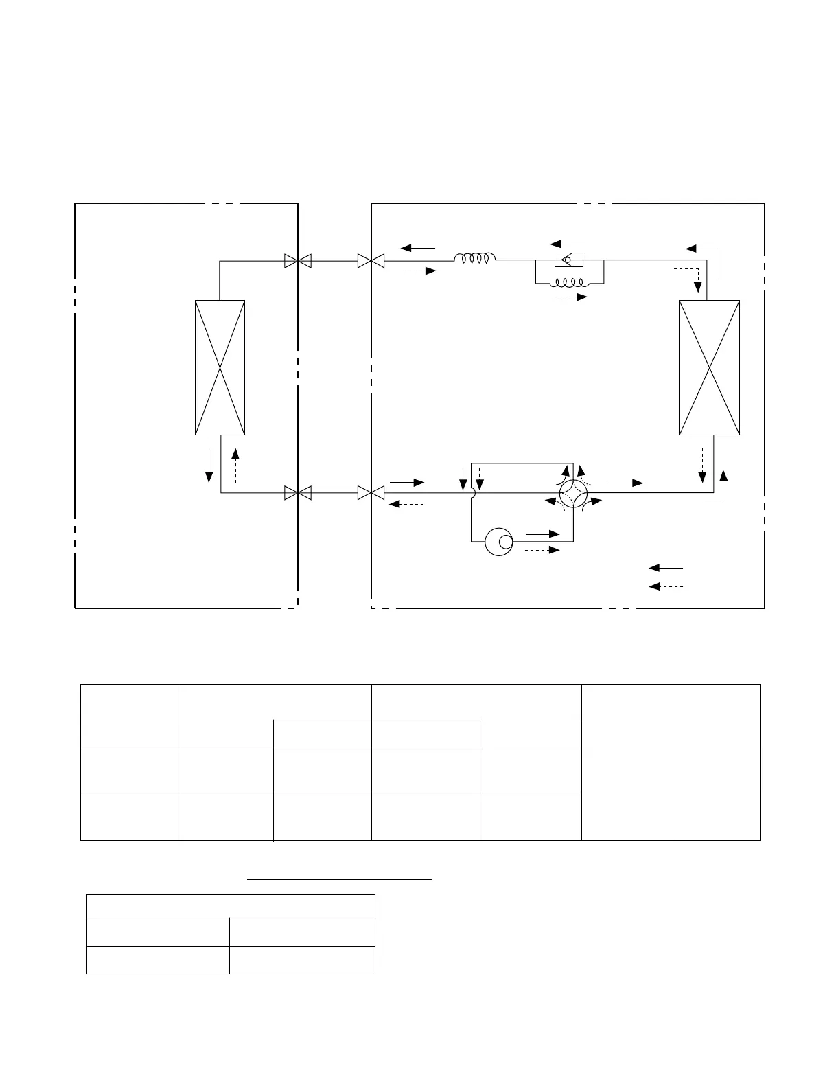
INDOOR UNIT
HEAT
EXCHANGER
(EVAPORATOR)
HEAT
EXCHANGER
(CONDENSER)
REVERSING
VALVE
COMPRESSOR
COOLING
HEATING
GAS SIDE
CAPILLARY TUBE
CHECK VALVE
LIQUID SIDE
OUTDOOR UNIT
• Cooling & Heating Models
MODEL
9K, 12K
(Cooling & Heating)
18K, 24K
(Cooling & Heating)
Pipe size(Diameter:ø) Piping length Elevation
Gas Liquid Rated Max Rated Max
1/2" 1/4" 7.62m(25ft) 15m(50ft) 5m(16ft) 8m(26ft)
5/8" 3/8" 7.62m(25ft) 15m(50ft) 5m(16ft) 8m(26ft)
For installation over rated, *a proper quantity of refrigerant should be added for each meter.
Ex) 18K: When installed at a distance of 15m, 295g of
refrigerant should be added.
(15-7.62) x 40g = 295g
a proper quantity of refrigerant
9K, 12K 20g
18K, 24K 40g
 Loading...