_ Installation Instructions Modular Blower I
Low Voltage Control Connections
The 24 volt power supply is provided by an internally wired low
voltage transformer which is standard on all models. If power
supply is 208 volt, the low voltage transformer must be rewired to
the 208 volt tap. See the unit wiring label.
Field supplied low voltage wiring enters the unit on the top left
hand corner.
Install the strain relief bushing (supplied with unit) in the hole.
Connect the field wiring at the screw terminals of the control
board. Refer to Figure 6.
Keep the low voltage wiring as short as possible inside the control
box.
Complete connections between indoor blower, outdoor section,
indoor thermostat and electronic outdoor thermostat (accessory)
according to instruction provided with the Condenser Installation
Instructions or those provided with the accessory and refer to
Figures 7 and 8.
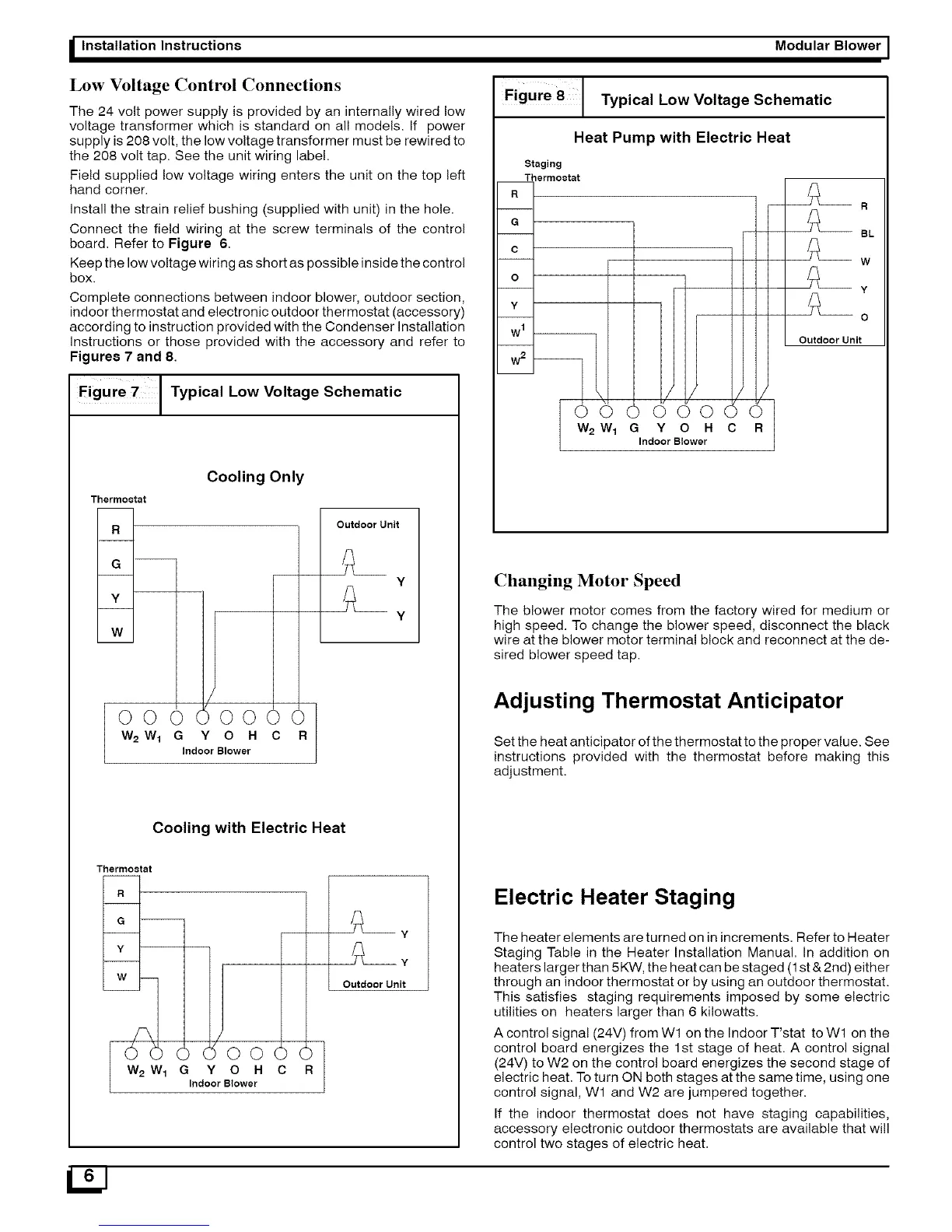
Figute 7 [ Typical Low Voltage Schematic
Therrnoctat
Cooling Only
R
G --
Y
W
ooo j
W2 W1 G R
Indoor Blower
/jJ
)00 )(
Y 0 H C
Outdoor Unit
Y
Y
Cooling with Electric Heat
Thermostat
R
G --
W
_-/_1( 00()(
W 2 W 1 G Y O H C R
Indoor Blower
-- y
Y
Outdoor Unit
LIJ
,gurel
Heat Pump with Electric Heat
Staging
T_ermo_tat
R I
--i
G I
O I
O I
Y I
W1 I
W 2 I--
Typical Low Voltage Schematic
(
R
1/
\
(_( 000
W 2 W 1 G Y O H C
Indoor Blower
R
BL
W
Y
O
Outdoor Unit
Changing Motor Speed
The blower motor comes from the factory wired for medium or
high speed. To change the blower speed, disconnect the black
wire at the blower motor terminal block and reconnect at the de-
sired blower speed tap.
Adjusting Thermostat Anticipator
Set the heat anticipator of the thermostat to the proper value. See
instructions provided with the thermostat before making this
adjustment.
Electric Heater Staging
The heater elements are turned on in increments. Refer to Heater
Staging Table in the Heater Installation Manual. In addition on
heaters larger than 5KW, the heat can be staged (1st & 2nd) either
through an indoor thermostat or by using an outdoor thermostat.
This satisfies staging requirements imposed by some electric
utilities on heaters larger than 6 kilowatts.
A control signal (24V) from Wl on the Indoor T'stat to W1 on the
control board energizes the 1st stage of heat. A control signal
(24V) to W2 on the control board energizes the second stage of
electric heat. To turn ON both stages at the same time, using one
control signal, W1 and W2 are jumpered together.
If the indoor thermostat does not have staging capabilities,
accessory electronic outdoor thermostats are available that will
control two stages of electric heat.