_ Installation Instructions
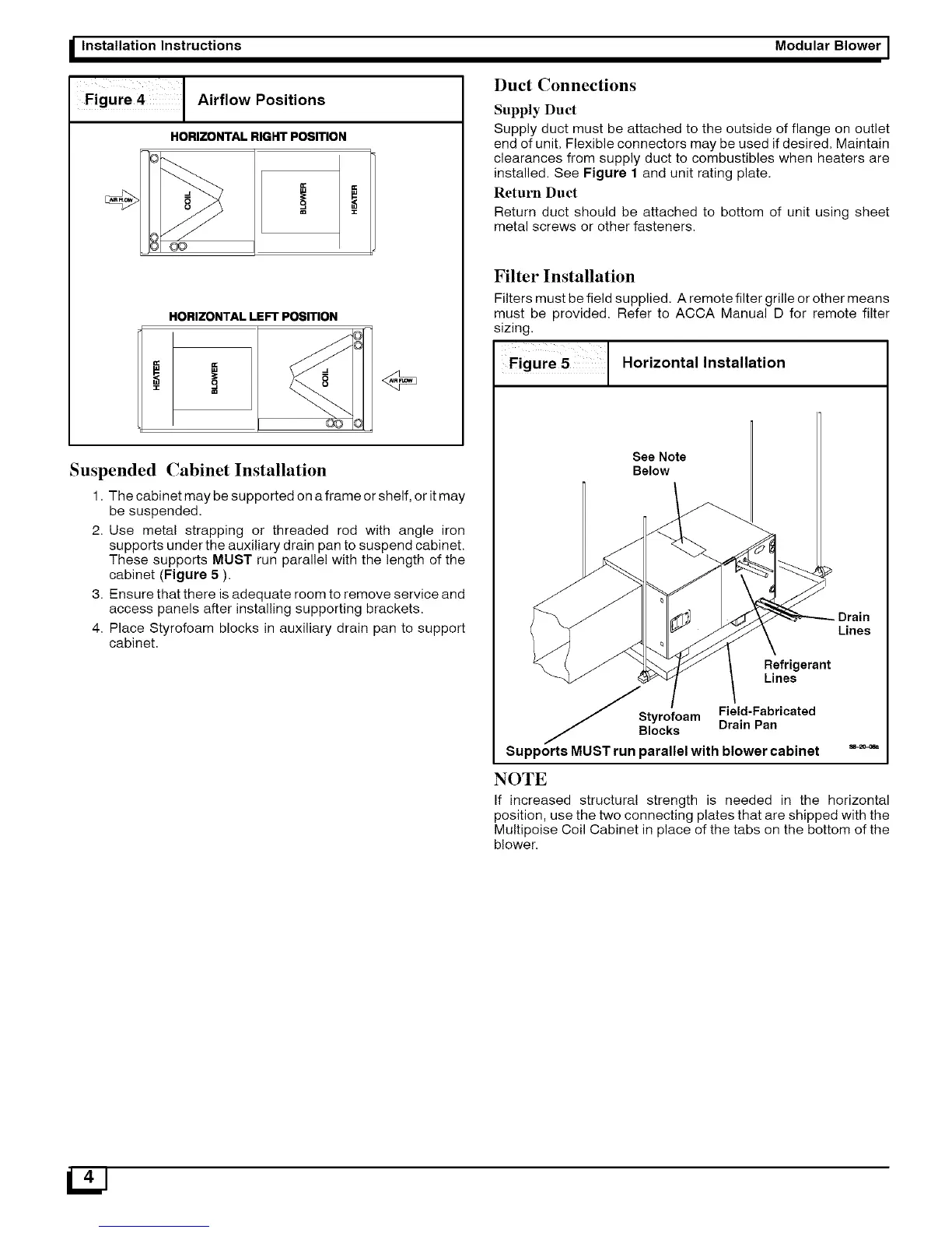
FigUre [ Airflow Positions
HORIZONTAL RIGHT POSITION
8®
HORIZONTAL LEFT POSITION
Suspended Cabinet Installation
1. The cabinet may be supported on a frame or shelf, or it may
be suspended.
2. Use metal strapping or threaded rod with angle iron
supports under the auxiliary drain pan to suspend cabinet.
These supports MUST run parallel with the length of the
cabinet (Figure 5 ).
3. Ensure that there is adequate room to remove service and
access panels after installing supporting brackets.
4. Place Styrofoam blocks in auxiliary drain pan to support
cabinet.
Modular Blower I
Duct Connections
Supply Duct
Supply duct must be attached to the outside of flange on outlet
end of unit. Flexible connectors may be used if desired. Maintain
clearances from supply duct to combustibles when heaters are
installed. See Figure 1 and unit rating plate.
Return Duct
Return duct should be attached to bottom of unit using sheet
metal screws or other fasteners.
Filter Installation
Filters must be field supplied, A remote filter grille or other means
must be provided. Refer to ACCA Manual D for remote filter
sizing.
Figure 5 Horizontal Installation
See Note
Below
Drain
Lines
Refrigerant
Lines
_Styrofoam Field-Fabricated
locks Drain Pan
Supports MUST run parallel with blower cabinet
NOTE
If increased structural strength is needed in the horizontal
position, use the two connecting plates that are shipped with the
Multipoise Coil Cabinet in place of the tabs on the bottom of the
blower.
12J