EasyManua.ls Logo

ICP MF12F1900A - User Manual

ICP MF12F1900A
11 pages
Print Icon
To Next Page IconTo Next Page
Loading...
INSTALLATION
INSTRUCTIONS
Models
MF08B1500A
MF12F1900A
MF16J2200A
MF20N2600A
With
AMF001NHA
Accessory No Heat Kit
Use ONLY factory listed electric heaters.
Modular Blower
(Electric Furnace)
Safety Labeling and Signal Words Cov
General Information / Installation ............ 2
Vertical Installations ........................ 2
Horizontal Installations ..................... 3
Condensate Drain .......................... 5
Refrigerant Orifice and Lines ................ 5
Electrical Wiring ............................ 6
Checks and Maintenance ................... 7
Blower Performance ........................ 8
Safety Labeling and Signal Words
Danger, Warning and Caution
The signal words DANGER, WARNING and CAUTION
are used to identify levels of hazard seriousness. The
signal word DANGER is only used on product labels to
signify an immediate hazard. The signal words WARN-
ING and CAUTION will be used on product labels and
throughout this manual and other manuals that may ap-
ply to the product.
DANGER - immediate hazards which WILL result in se-
vere personal injury or death.
WARNING - Hazards or unsafe practices which
COULD result in severe personal injury or death.
CAUTION - Hazards or unsafe practices which COULD
result in minor personal injury or product or property
damage.
Signal Words in Manuals
The signal word WARNING is used throughout this
manual in the following manner:
The signal word CAUTION is used throughout this
manual in the following manner:
CAUTION
Product Labeling
Signal words are used in combination with colors and/or
pictures on product labels.
Printed in U.S.A.
442 01 2202 02
June 2002
Question and Answer IconNeed help?

Do you have a question about the ICP MF12F1900A and is the answer not in the manual?

Summary

Safety Labeling and Signal Words

Danger, Warning, and Caution

Explains hazard levels used in manuals and on product labels.

Signal Words in Manuals

Explains the usage of signal words within the manual text.

Product Labeling

Describes how signal words are used on product labels.

General Information

Fire Hazard

Critical warning regarding clearances from combustible materials when heaters are installed.

Location

Guidance on selecting the optimal installation site for the unit.

Installations

Downflow Installations

Specific instructions for installing the unit in a downflow configuration.

Non-Ducted Return Air Closet Installation

Procedures for installing the unit in a closet environment.

Horizontal Left and Right Installations

Instructions for positioning the unit for horizontal airflow.

Duct Connections

Supply Duct

Guidelines for connecting the supply duct to the unit's outlet.

Return Duct

Instructions for attaching the return duct to the unit's bottom.

Filter Installation

Requirements for installing field-supplied air filters.

Electrical Connections

Overcurrent Protection

Requirements for providing overcurrent protection for the power supply wiring.

No Heat Kit Installation

Step-by-step guide to installing the accessory No Heat Kit.

Line Voltage Connections

Procedures for making line voltage wiring connections to the unit.

Grounding Connection

Instructions for establishing a proper ground connection for safety.

Low Voltage Control Connections

Changing Motor Speed

How to adjust the blower motor speed by changing wiring connections.

Adjusting Thermostat Anticipator

Guidance on setting the thermostat's heat anticipator value.

Electric Heater Staging

Explanation of how electric heater elements are staged for operation.

Air Flow Check

Measuring External Static Pressure

Steps to measure external static pressure for airflow assessment.

Temperature Rise Check

Checking Temperature Rise

Procedure to measure temperature difference between supply and return air.

Maintenance

Filters

Guidance on cleaning and inspecting system filters for efficiency.

Lubrication

Information regarding the permanent lubrication of blower motor bearings.

Condensate Drains

Checking condensate drain lines during the cooling season for proper flow.

Sequence Of Operation

Constant Blower Operation

Fan operates continuously regardless of heating or cooling calls.

Heating Operation

Controls heat stages based on thermostat demand.

Cooling Operation

Controls cooling operation for cooling/heat pump units.

Heat Pump Defrost Mode

Controls the defrost cycle for heat pump operation.

Emergency Heat Operation

Controls the emergency heat mode for heat pumps.

Limit Operation

Temperature Limit Function

How the temperature limit responds to over-temperature conditions in the duct.

Replacement Parts

Overview

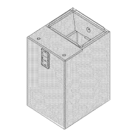
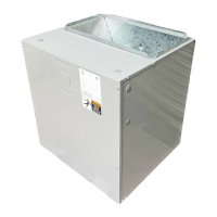
This document describes the installation, operation, and maintenance of a Modular Blower, also referred to as an Electric Furnace, designed for use with or without electric heat. The blower cabinet is compatible with cooling or heat pump operations and can be installed in upflow, downflow, or horizontal positions.

Function Description

The Modular Blower serves as the indoor air handler for heating and cooling systems. When equipped with an accessory No Heat Kit, it functions as a cooling or heat pump air handler without electric heat. When electric heaters are installed, it provides electric heating in addition to air circulation for cooling or heat pump operation. The unit circulates air through the indoor coil and ductwork, ensuring proper airflow for the system.

Important Technical Specifications

Models and Compatibility: The manual covers models MF08B1500A, MF12F1900A, MF16J2200A, and MF20N2600A, all compatible with the AMF001NHA Accessory No Heat Kit. The unit is designed to use ONLY factory-listed electric heaters.

Dimensions and Clearances (Figure 1):

  • Unit Widths: Ranging from 14-1/2" (2-2 1/2 Ton) for MF08 to 25" (5 Ton) for MF20.
  • Bottom Return Air Opening: Ranging from 14-1/4" x 20" (1 1/2-2 1/2 Ton) to 25-1/4" x 20" (5 Ton).
  • Clearances (No Heaters): 0" from all sides and supply duct, 20" recommended service from front.
  • Clearances (With Heaters): 0" from all sides, 1" from the first three feet of supply duct to combustibles, 0" from duct after three feet, 20" recommended service from front.

Electrical Specifications (Figure 6): The unit operates on 208V or 240V, single phase, 60 Hz.

  • Supply Circuit (Single, 60 Hz):
    • 240V: 6.0 AMPS motor, 6.0 AMPS total, 7.5 AMPS ampacity. Recommended 15 AMPS overcurrent protective device. Supply wire: 2x 14 AWG, 104 ft max length. Ground wire: 1x 14 AWG.
    • 208V: 6.0 AMPS motor, 6.0 AMPS total, 7.5 AMPS ampacity. Recommended 15 AMPS overcurrent protective device. Supply wire: 2x 14 AWG, 90 ft max length. Ground wire: 1x 14 AWG.
  • Low Voltage: 24 volt power supply provided by an internally wired transformer. If the power supply is 208 volt, the transformer must be rewired to the 208 volt tap.

Airflow Performance (Page 8): Airflow is measured in CFM (Cubic Feet per Minute) at various static pressures (SP IN, WG) and voltage settings (230V/208V) for different fan speed taps (LOW, MED, HIGH).

  • MF08 (e.g., 230V, HIGH tap): 1553 CFM at 0.3 SP IN, WG to 865 CFM at 1.0 SP IN, WG.
  • MF12 (e.g., 230V, HIGH tap): 1860 CFM at 0.3 SP IN, WG to 1178 CFM at 1.0 SP IN, WG.
  • MF16 (e.g., 230V, HIGH tap): 1912 CFM at 0.3 SP IN, WG to 1154 CFM at 1.0 SP IN, WG.
  • MF20 (e.g., 230V, HIGH tap): 2554 CFM at 0.3 SP IN, WG to 1606 CFM at 1.0 SP IN, WG.
  • Airflow Requirement: For proper system operation, airflow through the indoor coil should be between 350 and 450 cfm per ton of cooling capacity.
  • Temperature Rise: A temperature rise greater than 60 °F (33.3 °C) is not recommended. Maximum outlet air temperature for all models is 200 °F (93.3 °C).

Usage Features

Installation Flexibility (Figure 3, 4):

  • Multi-positional: Can be installed in upflow, downflow, or horizontal (left or right) positions without modifications.
  • Coil Attachment: The coil cabinet is secured to the blower cabinet using three tabs on the blower cabinet base.
  • Seal Strip: Foam seal strip is applied around the top of the coil cabinet for upflow/horizontal applications or around the bottom for downflow applications.
  • Non-Ducted Return Air: Can be installed in a closet with a false bottom or on an open platform for return air, subject to local codes and ACCA Manual D recommendations.
  • Suspended Installation: Can be supported on a frame, shelf, or suspended using metal strapping or threaded rod with angle iron supports under an auxiliary drain pan. Supports MUST run parallel with the cabinet length.

Electrical Connections (Figure 6):

  • Line Voltage: Connections are made to the heater accessory or lugs on the No Heat Kit, requiring copper wire. A hole for 1/2" or 3/4" conduit fitting is provided for wiring entry.
  • Low Voltage: 24V wiring connects to screw terminals on the control board. Strain relief bushing is supplied.
  • Grounding: Copper conductor(s) from the ground lug on the No Heat Kit or electric heater to a grounded connection in the electric service panel or a grounding rod.
  • Overcurrent Protection: Power supply wiring MUST have overcurrent protection (fuses or circuit breakers). For blower cabinets without heaters, a 15 amp circuit may be used.

No Heat Kit Installation (Figure 6): If electric heat is not used, the accessory No Heat Kit must be installed. This involves attaching adapter and filler plates to a bracket and securing the kit with screws, then connecting its plug to the receptacle on the control board.

Motor Speed Adjustment: The blower motor comes factory-wired for medium or high speed. Speed can be changed by disconnecting the black wire at the blower motor terminal block and reconnecting to the desired speed tap.

Electric Heater Staging (Figure 8): Heater elements are turned on in increments. For heaters larger than 5KW, heat can be staged (1st & 2nd) via an indoor or outdoor thermostat. A 24V control signal from W1 on the indoor thermostat energizes the 1st stage, and W2 energizes the 2nd stage. W1 and W2 can be jumpered for simultaneous staging.

Sequence of Operation (Page 9): The manual details the control logic for various modes:

  • Electric Heat Only: Fan On/Off with G, 1st/2nd stage heat with G & W1 & W2 (with 6-second delay for heat off).
  • Cooling Only Unit With Electric Heat: Fan On/Off with G, Compressor On/Off with Y & G (with 60-second delay for compressor off), 1st/2nd stage heat with G & W1 & W2 (with 6-second delay for heat off).
  • Heat Pump With Electric Heat: Compressor On/Off with Y & G & O (reversing valve energized for cooling), Compressor On/Off with Y & G (for heating), 1st/2nd stage heat with Y & G & W1 & W2 (for maintaining temperature), reversing valve switches for defrost mode, and 1st/2nd stage heat for emergency heat.

Limit Operation: The temperature limit responds to over-temperature conditions. If tripped, heater relays de-energize, and the fan relay energizes. Multiple trips can lead to soft or hard lockout, which disables heater relays. Power cycling clears the lockout.

Maintenance Features

Filters:

  • Field Supplied: Filters must be supplied by the installer.
  • Regular Cleaning: Filters must be cleaned when dirty, inspected at least once per month. Frequency depends on operating hours and atmospheric conditions. Clean filters maintain unit efficiency.

Lubrication: The bearings of the blower motor are permanently lubricated, requiring no field lubrication.

Condensate Drains:

  • Seasonal Check: During the cooling season, condensate drain lines should be checked to ensure proper flow from the primary drain.
  • Secondary Drain Overflow: If condensate flows from the secondary drain, the unit should be promptly shut off, and the condensate pan and drains cleaned to ensure a free-flowing primary drain.
  • Auxiliary Drain Pan: A field-fabricated auxiliary drain pan with a separate drain is REQUIRED for installations over a finished living space or in any area that may be damaged by overflow from the main drain pan. Local codes may require an auxiliary drain pan for ANY horizontal installation.

Air Flow Check (Figure 9):

  • External Static Pressure Measurement: Set up to measure external static pressure at supply and return duct connections using an inclined manometer or draft gauge.
  • Procedure: Drill holes in ducts for pressure taps, ensure clean coil and filter, open registers, determine static pressure, and refer to Air Flow Data tables (page 8) to select the appropriate motor speed tap. Recheck static pressure after speed changes.

Temperature Rise Check:

  • Procedure: Place thermometers in supply and return air ducts, open all registers and dampers, set thermostat to HEAT and high temperature, turn ON electric power, operate for at least 5 minutes, then check temperature rise.
  • Recommendation: Temperature rise should not exceed 60 °F (33.3 °C). Maximum outlet air temperature is 200 °F (93.3 °C). Seal any holes created in ducts after the check.

ICP MF12F1900A Specifications

General IconGeneral
BrandICP
ModelMF12F1900A
CategoryBlower
LanguageEnglish

Related product manuals