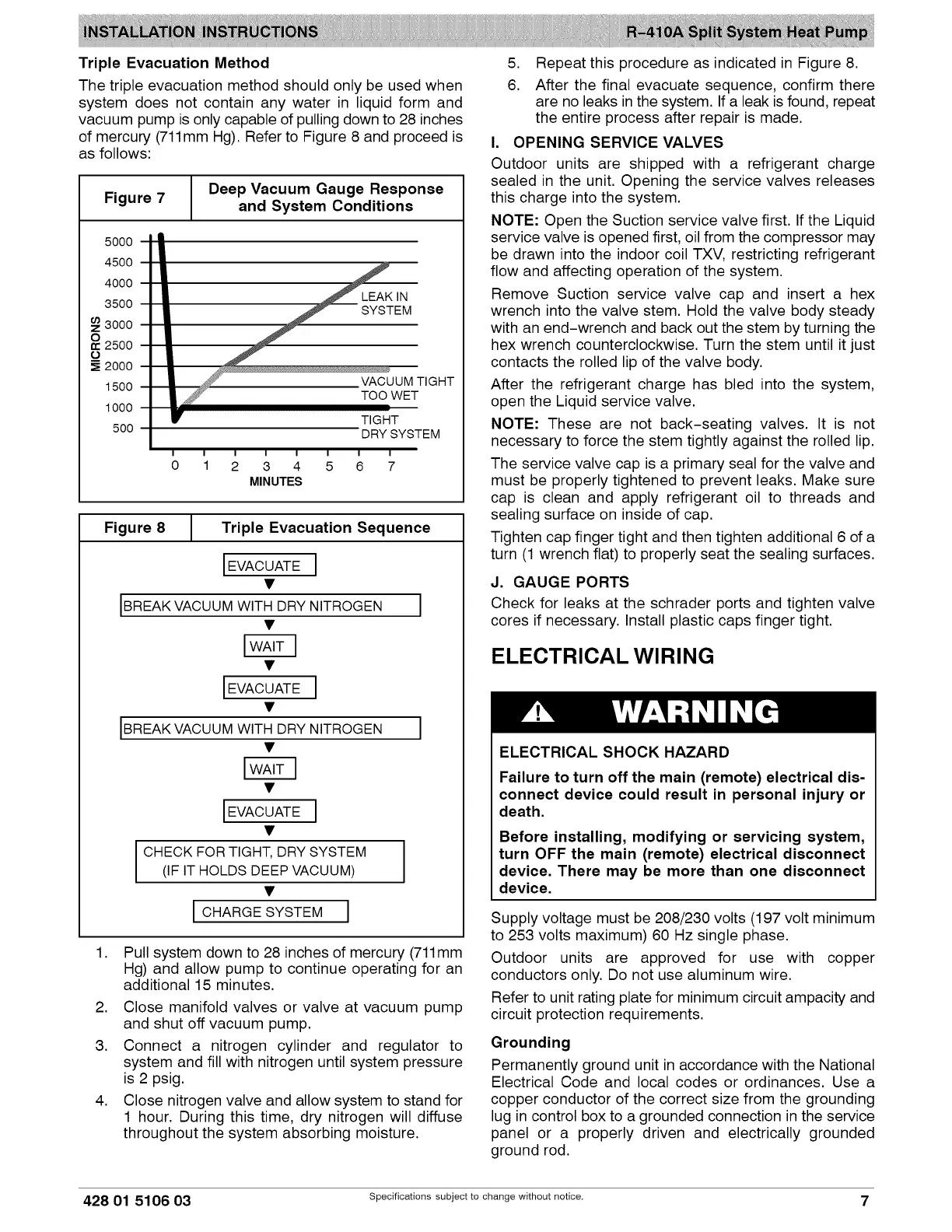
Triple Evacuation Method
The triple evacuation method should only be used when
system does not contain any water in liquid form and
vacuum pump is only capable of pulling down to 28 inches
of mercury (711mm Hg). Refer to Figure 8 and proceed is
as follows:
Figure 7
Deep Vacuum Gauge Response
and System Conditions
5000
4500
4000
3500
3000
2500
O
2000
1500
1000
500
--4
TIGHT
ET
DRY SYSTEM
I I I I I I I I
0 1 2 3 4 5 6 7
MINUTES
Figure 8
Triple Evacuation Sequence
IEVACUATE I
[BREAKVACUUM WITH DRY NITROGEN l
IEVACUATE I
IEVACUATE I
CHECK FORTIGHT, DRYSYSTEM I
I
(IF IT HOLDS DEEPVACUUM)
I CHARGESYSTEM I
.
Pull system down to 28 inches of mercury (711mm
Hg) and allow pump to continue operating for an
additional 15 minutes.
2. Close manifold valves or valve at vacuum pump
and shut off vacuum pump.
3. Connect a nitrogen cylinder and regulator to
system and fill with nitrogen until system pressure
is 2 psig.
4. Close nitrogen valve and allow system to stand for
1 hour. During this time, dry nitrogen will diffuse
throughout the system absorbing moisture.
5.
6.
Repeat this procedure as indicated in Figure 8.
After the final evacuate sequence, confirm there
are no leaks in the system. If a leak is found, repeat
the entire process after repair is made.
I. OPENING SERVICE VALVES
Outdoor units are shipped with a refrigerant charge
sealed in the unit. Opening the service valves releases
this charge into the system.
NOTE: Open the Suction service valve first. If the Liquid
service valve is opened first, oil from the compressor may
be drawn into the indoor coil TXV, restricting refrigerant
flow and affecting operation of the system.
Remove Suction service valve cap and insert a hex
wrench into the valve stem. Hold the valve body steady
with an end-wrench and back out the stem by turning the
hex wrench counterclockwise. Turn the stem until it just
contacts the rolled lip of the valve body.
After the refrigerant charge has bled into the system,
open the Liquid service valve.
NOTE: These are not back-seating valves. It is not
necessary to force the stem tightly against the rolled lip.
The service valve cap is a primary seal for the valve and
must be properly tightened to prevent leaks. Make sure
cap is clean and apply refrigerant oil to threads and
sealing surface on inside of cap.
Tighten cap finger tight and then tighten additional 6 of a
turn (1 wrench flat) to properly seat the sealing surfaces.
J. GAUGE PORTS
Check for leaks at the schrader ports and tighten valve
cores if necessary. Install plastic caps finger tight.
ELECTRICAL WIRING
ELECTRICAL SHOCK HAZARD
Failure to turn off the main (remote) electrical dis-
connect device could result in personal injury or
death.
Before installing, modifying or servicing system,
turn OFF the main (remote) electrical disconnect
device. There may be more than one disconnect
device.
Supply voltage must be 208/230 volts (197 volt minimum
to 253 volts maximum) 60 Hz single phase.
Outdoor units are approved for use with copper
conductors only. Do not use aluminum wire.
Refer to unit rating plate for minimum circuit ampacity and
circuit protection requirements.
Grounding
Permanently ground unit in accordance with the National
Electrical Code and local codes or ordinances. Use a
copper conductor of the correct size from the grounding
lug in control box to a grounded connection in the service
panel or a properly driven and electrically grounded
ground rod.
428 01 5106 03 Specifications subject to change without notice. 7
 Loading...