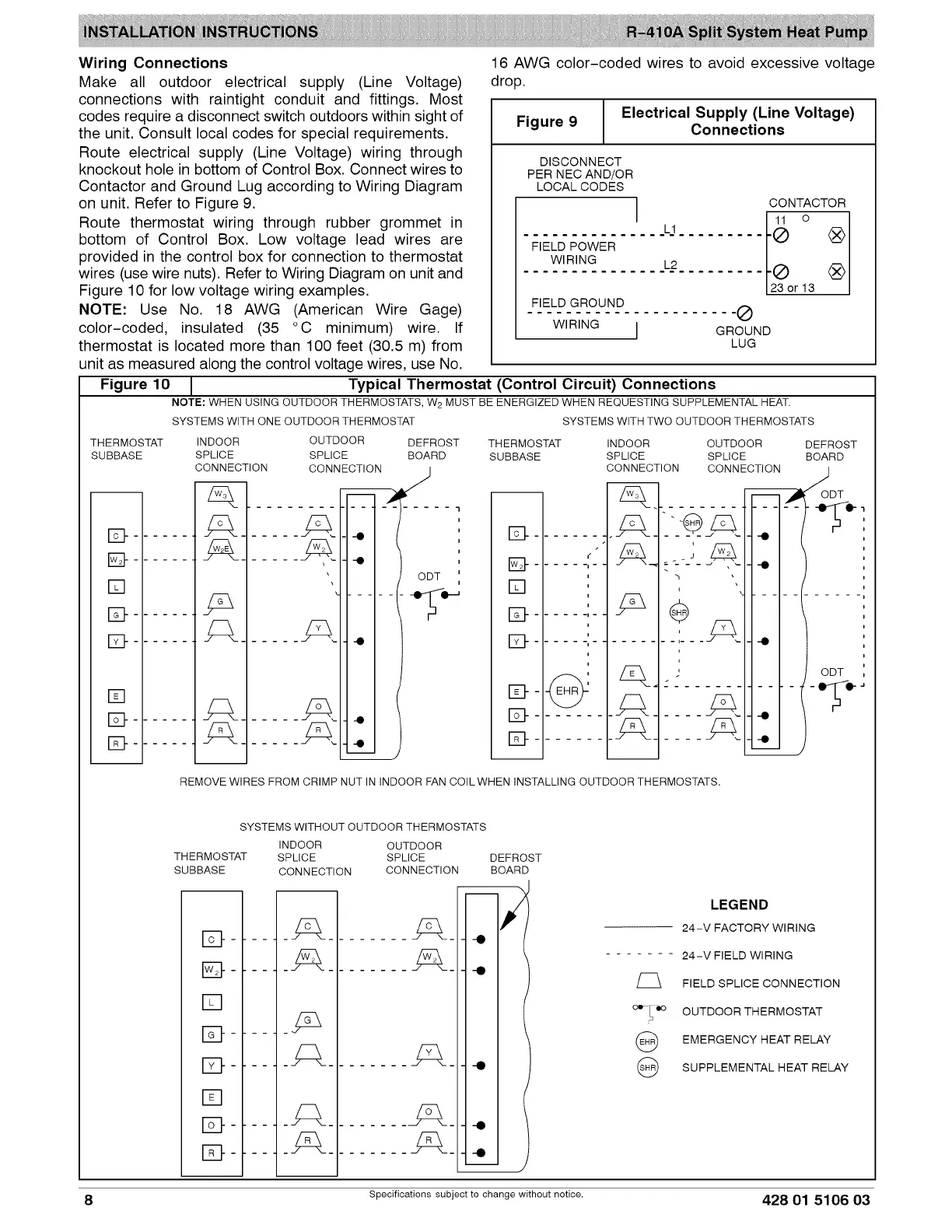
Wiring Connections
Make all outdoor electrical supply (Line Voltage)
connections with raintight conduit and fittings. Most
codes require a disconnect switch outdoors within sight of
the unit. Consult local codes for special requirements.
Route electrical supply (Line Voltage) wiring through
knockout hole in bottom of Control Box. Connect wires to
Contactor and Ground Lug according to Wiring Diagram
on unit. Refer to Figure 9.
Route thermostat wiring through rubber grommet in
bottom of Control Box. Low voltage lead wires are
provided in the control box for connection to thermostat
wires (use wire nuts). Refer to Wiring Diagram on unit and
Figure 10 for low voltage wiring examples.
NOTE: Use No. 18 AWG (American Wire Gage)
color-coded, insulated (35 °C minimum) wire. If
thermostat is located more than 100 feet (30.5 m) from
unit as measured along the control voltage wires, use No.
16 AWG color-coded wires to avoid excessive voltage
drop.
Electrical Supply (Line Voltage)
Figure 9
Connections
DISCONNECT
PER NEC AND/OR
LOCAL CODES
L1
FIELD POWER
WIRING L2
FIELD GROUND
WIRING I
CONTACTOR
11 o
-@ ®
-@ ®
23 or 13
-®
GROUND
LUG
Figure 10 Typical Thermostat (Control Circuit) Connections
NOTE: WHEN USING OUTDOOR THERMOSTATS, W 2 MUST BE ENERGIZED WHEN REQUESTING SUPPLEMENTAL HEAT.
SYSTEMS WITH ONE OUTDOOR THERMOSTAT SYSTEMS WITH TWO OUTDOOR THERMOSTATS
THERMOSTAT INDOOR OUTDOOR THERMOSTAT INDOOR OUTDOOR
SUBBASE SPLICE SPLICE SUBBASE SPLICE SPLICE
CONNECTION CONNECTION CONNECTION CONNECTION
z_
D _ .....
E3- Z_ .....
[]
D
[]
133- _ .....
133- _ .....
. -Q
\
\
DEFROST
BOARD
i
i
i
i
i
ODT '
i
B ......... ..
• ;z3_
IS} ...... ','- _. .... ,_-
t "1
[] : , ,.....
D
E_ ' -_-_
t
t
...........
D .E__..... /ss_.
DEFROST
BOARD
/
ODT
i
i
i
i
i
i
i
i
-i
i
i
i
i
i
i
i
ODT ,
__I
REMOVE WIRES FROM CRIMP NUT IN INDOOR FAN COILWHEN INSTALLING OUTDOOR THERMOSTATS.
SYSTEMS WITHOUT OUTDOOR THERMOSTATS
INDOOR OUTDOOR
THERMOSTAT SPLICE SPLICE DEFROST
SUBBASE CONNECTION CONNECTION BOARD
-;
_"----0
_-'--- -0
_--- 4
D ...... _
[]
I_-...... -'_
D ...... S___
[]
O0 -¸! qlO
@
@
LEGEND
24-V FACTORY WIRING
24-V FIELD WIRING
FIELD SPLICE CONNECTION
OUTDOOR THERMOSTAT
EMERGENCY HEAT RELAY
SUPPLEMENTAL HEAT RELAY
- -0
- 4
8 Specifications subject to change without notice. 428 01 5106 03
 Loading...