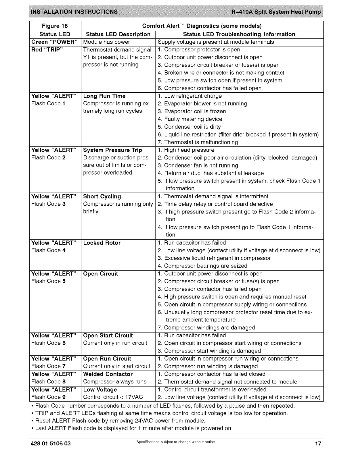
Figure 18
Status LED
Green "POWER"
Red "TRIP"
Yellow "ALERT"
Flash Code 1
Yellow "ALERT"
Flash Code 2
Yellow "ALERT"
Flash Code 3
Yellow "ALERT"
Flash Code 4
Yellow "ALERT"
Flash Code 5
Status LED Description
Module has power
Thermostat demand signal
Y1 is present, but the com-
pressor is not running
Long Run Time
Compressor is running ex-
tremely long run cycles
System Pressure Trip
Discharge or suction pres-
sure out of limits or com-
pressor overloaded
Short Cycling
Compressor is running only
briefly
Locked Rotor
Open Circuit
Yellow "ALERT" Open Start Circuit
Flash Code 6 Current only in run circuit
Yellow "ALERT" Open Run Circuit
Flash Code 7 Current only in start circuit
Yellow "ALERT" Welded Contactor
Flash Code 8 Compressor always runs
Yellow "ALERT" Low Voltage
Flash Code 9 Control circuit < 17VAC
Comfort Alert TM Diagnostics (some models)
Status LED Troubleshooting Information
Supply voltage is present at module terminals
1. Compressor protector is open
2. Outdoor unit power disconnect is open
3. Compressor circuit breaker or fuse(s) is open
4. Broken wire or connector is not making contact
5. Low pressure switch open if present in system
6. Compressor contactor has failed open
1. Low refrigerant charge
2. Evaporator blower is not running
3. Evaporator coil is frozen
4. Faulty metering device
5. Condenser coil is dirty
6. Liquid line restriction (filter drier blocked if present in system)
7. Thermostat is malfunctioning
1. High head pressure
2. Condenser coil poor air circulation (dirty, blocked, damaged)
3. Condenser fan is not running
4. Return air duct has substantial leakage
5. If low pressure switch present in system, check Flash Code 1
information
1. Thermostat demand signal is intermittent
2. Time delay relay or control board defective
3. If high pressure switch present go to Flash Code 2 informa-
tion
4. If low pressure switch present go to Flash Code 1 informa-
tion
1. Run capacitor has failed
2. Low line voltage (contact utility if voltage at disconnect is low)
3. Excessive liquid refrigerant in compressor
4. Compressor bearings are seized
1. Outdoor unit power disconnect is open
2. Compressor circuit breaker or fuse(s) is open
3. Compressor contactor has failed open
4. High pressure switch is open and requires manual reset
5. Open circuit in compressor supply wiring or connections
6. Unusually long compressor protector reset time due to ex-
treme ambient temperature
7. Compressor windings are damaged
1. Run capacitor has failed
2. Open circuit in compressor start wiring or connections
3. Compressor start winding is damaged
1. Open circuit in compressor run wiring or connections
2. Compressor run winding is damaged
1. Compressor contactor has failed closed
2. Thermostat demand signal not connected to module
1. Control circuit transformer is overloaded
2. Low line voltage (contact utility if voltage at disconnect is low)
• Flash Code number corresponds to a number of LED flashes, followed by a pause and then repeated.
• TRIP and ALERT LEDs flashing at same time means control circuit voltage is too low for operation.
• Reset ALERT Flash code by removing 24VAC power from module.
• Last ALERT Flash code is displayed for 1 minute after module is powered on.
428 01 5106 03 specificationssubjectto change without notice. 17
 Loading...