SERVICE AND TECHNICAL SUPPORT MANUAL Gas Furnace: N9MSB
Specifications subject to change without notice.
440 04 4413 03 27
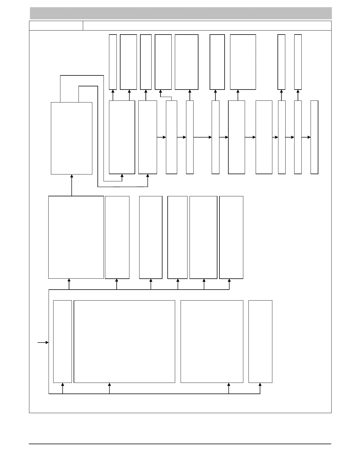
Figure 16 (CONT.)
Troubleshooting Guide − Flow Chart
1 + 2 BLOWER ON AFTER POWER UP –
(115V OR 24V) – Norm
al operation.
Blower runs for 90 seconds, if unit is
powered up during a call for heat (R-
W/W1 closed) or when (R-W/W1 opens)
d
u
ring the blower on-delay period.
6 + 1 IGNITION LOCKOUT – System failed to
ignite gas and prove flame in 4
attemp
ts. Control will auto-reset after 3
hours. Refer to status code #6.
5 ABNORMAL FLAME-PROVING SIGNAL
Flame is proved while gas valve is de-
energi
zed. Inducer will run until fault is
cleared. Check for:
- Stuck open or leaky gas valve.
2 PRESSURE SWITCH DID NOT OPEN –
Check for:
- Obstruct
ed pressure tube.
- Pressure switch stuck closed.
3 LPS or HPS PRESSURE SWITCH DID
NOT CLOSE OR REOPENED – If opens
during blower on-delay period, blower will
come on for the selected blower off-delay.
If LPS open longer than 5 minutes,
induc
er
shuts off for 15 minutes before
retry. If HPS open for one minute, then
furnace will lockout (after the successive
trials) for three hours before retry .
Check for:
- Proper vent sizing.
- Air leak between vestibule and blower
compartment.
- Low inlet gas pressure (if LGPS used).
- Disconnected or obstructed pressure
tubi
ng.
- Defective or miswired pressure switches
- Excessive wind.
- P
l
ugged condensate drain
- Water in vent piping, possible sagging
pipe
-
Restri
cted vent.
- Defective Inducer motor.
- Low inducer voltage (115 VAC)
4 LIMIT CIRCUIT FAULT – Indicates the
limit, flame rollout is open. Blower will run
for 4 min. or until open switch remakes
whichever is longer. If open longer than 3
min, code changes to lockout #7. If open
less than 3 min. status code #4 continues
to flash until blower shuts off. Flame
roll
o
ut switch requires manual reset.
Check for:
- Loose blower wheel.
-
Defective switch or connections.
- Dirty filter or restricted duct system.
- Improper gas input adjustment
- Improper limit switch or no limit gasket
To determine whether the problem is in
the gas valve, igniter, or flame sensor the
system can be operated in component
test mode. To check the igniter, remove
the R thermostat connection from the
control, reset power, start the component
test.
Do
es the igniter glow orange/white
by the end of the 15 second warm-up
period?
Unplug igniter harness from control and
repeat component test. Check for 115V
betwee
n connector P2 (HSI) and
NEUTRAL-L2 on the control. Was 115V
presen
t for the 15 second period?
Check connections and retry.
If current is near typical value
(4.0-6.0A DC nominal) and
bur
ners will not stay on,
replace control.
Clean flame sensor with fine steel wool
and recheck current. Nominal current is
4.0 to 6.0A DC.
Is current near typical value?
Replace electrode.
Will main burners ignite and stay on? Replace furnace control.
Fixed.
NO
YES
YES
YES
NO
NO
Replace furnace control.
Check for continuity in the
harness and igniter. Replace
defective component.
Reconnect the R thermostat lead and set
thermostat to call for heat. Connect
voltmeter across gas valve connections.
Does gas valve receive 24V?
Does gas valve open and allow gas to
flow?
Do the main burners ignite?
Do the main burners stay on?
Allow blower to come on and
repeat test to check for
intermittent operation.
Check that gas valve electric
switch is turned on. Replace
valve.
Check connections. If OK,
replace control.
Check for:
- Inadequate flame carryover
or rough ignition.
- Low inlet gas pressure.
- Proper firing rate.
Repeat call for heat and check flame
sensor current during trial for ignition
period. Is the DC current below 0.5A?
YES
YES
YES
YES
YES
NO
NO
NO
NO
NO
NO
6 IGNITION PROVING FAILURE – If flame is
not sensed during the trial for ignition
period, the control will repeat the ignition
sequence 3 more times before lockout #6 +
1 occurs. If flame signal is lost during the
blower on-delay period, blower will come on
for the selected blower off-delay. Check
th
e fo
llowing before going to the next step.
- Gas valve turned off .
- Man
ual shut-off valve open?
- Green/Yellow wire MUST be connected
to furnace sheet metal.
- Flame sensor must not be grounded.
10 POLARITY – Check for correct line
voltage polarity. If units are twinned,
check fo
r proper low-voltage (24V)
transformer phasing.
7 LIMIT CIRCUIT LOCKOUT – Lockout
occurs if the limit, flame rollout is open
long
er than 3 minutes. Control will auto-
reset after 3 hours. Refer to status code
#4.
8 GAS HEATING LOCKOUT – Control will
NOT auto reset. Turn off power and wait
5 minutes to retry. Check for:
- Stuck closed gas valve relay on control.
-
Miswire or short to gas valve wire.
YES
unless noted on switch.
L12F045
 Loading...
