PROPANE
MEAN ELEVATION FEET ABOVE SEA LEVEL
HEATING VALUE 0 to 2000 to 3000 to 4000 to 5000 to 6000 to 7000 to
BTU/CU. FT. 1999 2999 3999 4999 5999 6999 8000
2500 10.0" wc 10.0" wc 9.4" wc 10.0" wc 9.8" wc 8.8" wc 7.9" wc
Orifice Size #54 #54 #54 #55 #55 #55 #55
NOTE:NATURAL GAS DATA BASED ON 0.60 SPECIFIC
GRAVITY. PROPANE DATA BASED ON 1.53
SPECIFIC GRAVITY. FOR FUELS WITH DIFFERENT
SPECIFIC GRAVITY CONSULT THE LATEST EDITION
OF THE NATIONAL FUEL GAS CODE ANSI Z223.1
and CAN B149.
Changing Orifices
1 . After disconnecting power and gas supply to the furnace,
remove the access door, exposing gas valve and burner
compartment.
2. Disconnect gas line, pilot tubing from gas valve so manifold
can be removed.
3. Disconnect wiring at gas valve. Be sure to note the proper
location of any and all electrical wiring disconnected.
4. Replace the four (4) screws holding the manifold and gas
valve to the manifold supports. Do not discard any screws.
See Figure 6.
Figure 6 Manifold
25_20_95
5. Carefully remove the manifold assembly.
6. Remove the orifices from the manifold and replace them
with proper sized orifices.
Figure 7 Clearances
Measure 11/8" (27mm) from face
of orifice to the back side of the
manifold.
7. Tighten orifices so there is 11/8" from the face of the orifice
to the back side of the manifold. See Figure 7.
8. Reassemble all parts in reverse order as removed. Be sure
to engage the main burner orifices in the proper opening in
the burners.
9. After reassembling, turn gas on and check all joints for gas
leaks using a soapy solution. All leaks must be repaired im-
mediately.
Gas Piping Requirements
1 . Install gas piping in accordance with local codes, or in the
absence of local codes, the applicable national codes.
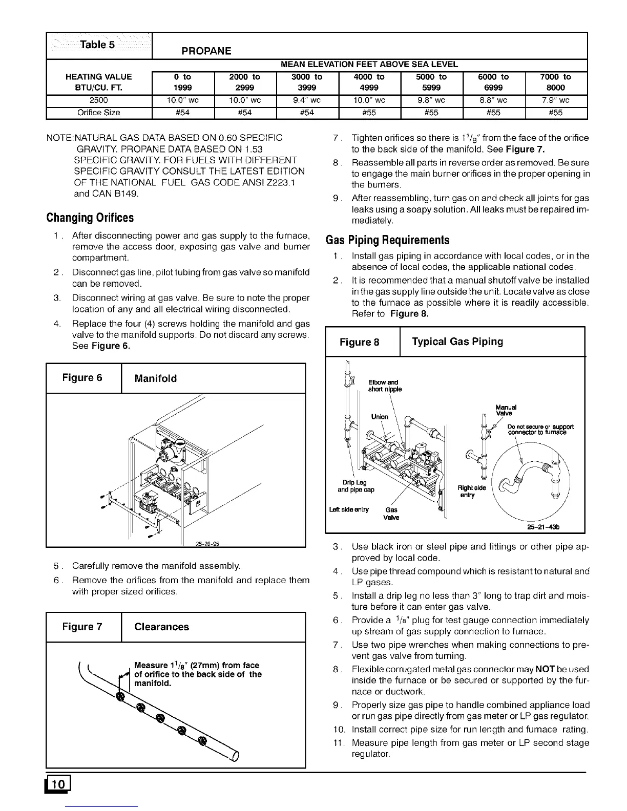
2. It is recommended that a manual shutoff valve be installed
in the gas supply line outside the unit. Locate valve as close
to the furnace as possible where it is readily accessible.
Refer to Figure 8.
Figure 8 Typical Gas Piping
Elbow and
short nipple
DripLeg
and pipecap
Leftsideen#y Gas
Valve
Righ_side
enW
Manual
Valve
DO not secure or support
connector to furnace
25-21-43b
3. Use black iron or steel pipe and fittings or other pipe ap-
proved by local code.
4. Use pipe thread compound which is resistant to natural and
LP gases.
5. Install a drip leg no less than 3" long to trap dirt and mois-
ture before it can enter gas valve.
6. Provide a 1/8" plug for test gauge connection immediately
up stream of gas supply connection to furnace.
7. Use two pipe wrenches when making connections to pre-
vent gas valve from turning.
8. Flexible corrugated metal gas connector may NOT be used
inside the furnace or be secured or supported by the fur-
nace or ductwork.
9. Properly size gas pipe to handle combined appliance load
or run gas pipe directly from gas meter or LP gas regulator.
10. Install correct pipe size for run length and furnace rating.
11. Measure pipe length from gas meter or LP second stage
regulator.