NOTE:NATURALGASDATABASEDON0.60SPECIFIC
GRAVITY.PROPANEDATABASEDON1.53
SPECIFICGRAVITY.FORFUELSWITHDIFFERENT
SPECIFICGRAVITYCONSULTTHELATESTEDITION
OFTHENATIONALFUELGASCODEANSIZ223.1
andCANB149.
Changing Orifices
1. After disconnecting power and gas supply to the furnace, re-
move the access door, exposing gas valve and burner
compartment.
2. Disconnect gas line and pilot tubing from gas valve so man-
ifold can be removed.
3. Disconnect wiring at gas valve. Be sure to note the proper
location of any and all electrical wiring disconnected.
4. Remove the four (4) screws holding the manifold and gas
valve to the manifold supports. Do not discard any screws.
See Figure 7.
Gas Piping Requirements
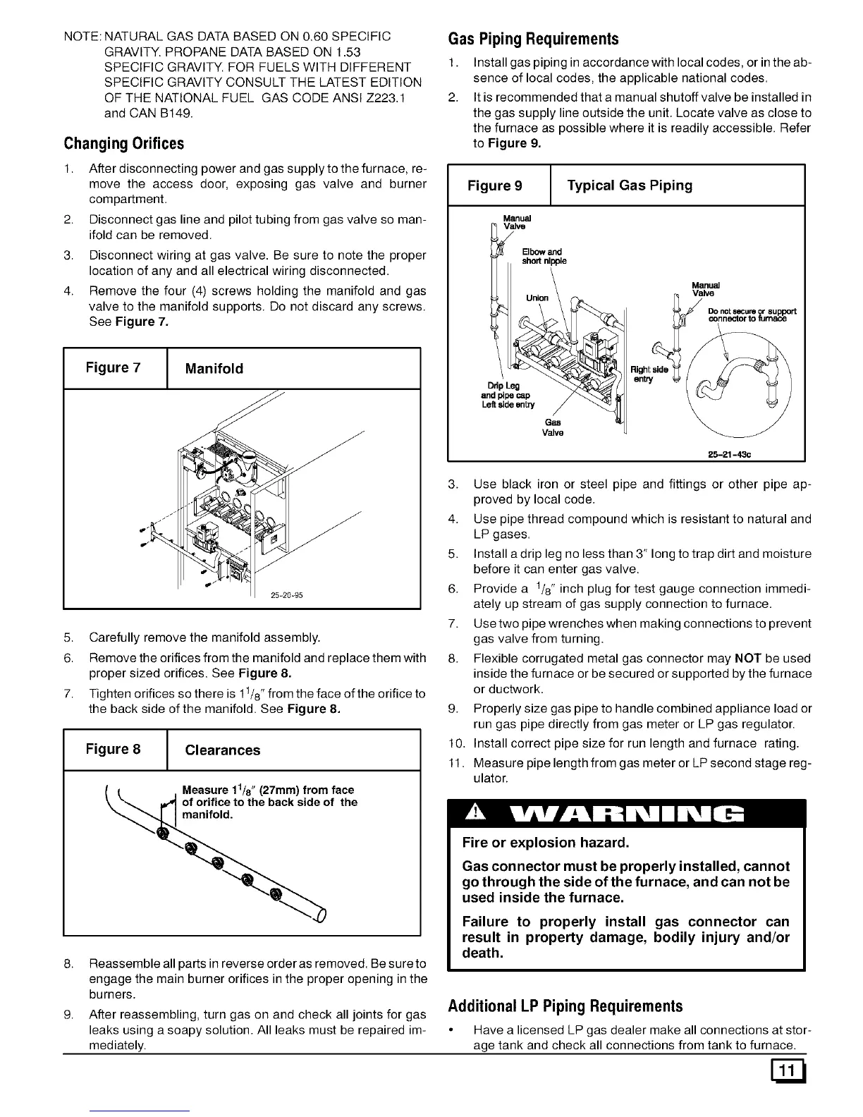
1. Install gas piping in accordance with local codes, or in the ab-
sence of local codes, the applicable national codes.
2. It is recommended that a manual shutoff valve be installed in
the gas supply line outside the unit. Locate valve as close to
the furnace as possible where it is readily accessible. Refer
to Figure 9.
Figure 7
Manifold
25-20-95
5. Carefully remove the manifold assembly.
6. Remove the orifices from the manifold and replace them with
proper sized orifices. See Figure 8.
7. Tighten orifices so there is 11/8"from the face of the orifice to
the back side of the manifold. See Figure 8.
Figure 8 Clearances
Measure 11/8" (27mm) from face
of orifice to the back side of the
manifold.
Reassemble all parts in reverse order as removed. Be sure to
engage the main burner orifices in the proper opening in the
burners.
Figure 9 Typical Gas Piping
Manual
V_lve
Elbowand
F1 shortnipple
_Union =
and pipecap
Gas
Valve
Manu=
Valve
DOnotsecureor support
connectortofumane
25-21-43c
3. Use black iron or steel pipe and fittings or other pipe ap-
proved by local code.
4. Use pipe thread compound which is resistant to natural and
LP gases.
5. Install a drip leg no less than 3" long to trap dirt and moisture
before it can enter gas valve.
6. Provide a 1/8" inch plug for test gauge connection immedi-
ately up stream of gas supply connection to furnace.
7. Use two pipe wrenches when making connections to prevent
gas valve from turning.
8. Flexible corrugated metal gas connector may NOT be used
inside the furnace or be secured or supported by the furnace
or ductwork.
9. Properly size gas pipe to handle combined appliance load or
run gas pipe directly from gas meter or LP gas regulator.
10. Install correct pipe size for run length and furnace rating.
11. Measure pipe length from gas meter or LP second stage reg-
ulator.
Fire or explosion hazard.
Gas connector must be properly installed, cannot
go through the side of the furnace, and can not be
used inside the furnace.
Failure to properly install gas connector can
result in property damage, bodily injury and/or
death.
After reassembling, turn gas on and check all joints for gas
leaks using a soapy solution. All leaks must be repaired im-
mediately.
Additional LP Piping Requirements
• Have a licensed LP gas dealer make all connections at stor-
age tank and check all connections from tank to furnace.
 Loading...
