• Ifcoppertubingisused,itMUST comply with limitation set in
Local Codes, or in the absence of local codes, the gas codes
of the country having jurisdiction. See Appendix.
• Two-stage regulation of LP gas is recommended.
• Do not use an open flame to test for gas leaks. Fire or explo-
sion could occur.
• Correct even the smallest leak at once.
FinalCheck
• Test all pipe for leaks.
• If orifices where changed, make sure they are checked for
leaks.
• During pressure testing of gas piping system, observe the
following:
a. If test pressure does not exceed 1/2" PSIG, isolate the fur-
nace by closing its individual manual shutoff valve.
b. Iftest pressure exceeds 1/2"PSIG, the furnace and its indi-
vidual shutoff valve must be disconnected from the gas sup-
ply system.
• To check for leaks apply soap suds or a liquid detergent to
each joint. Bubbles forming indicate a leak.
Fire or explosion hazard.
Liquid petroleum (LP) gas is heavier than air and
will settle and remain in low areas and open
depressions.
Thoroughly ventilate area and dissipate gas. Do
NOT use a match or open flame to test for leaks,
or attempt to start up furnace before thoroughly
ventilating area.
An open flame or spark can result in property
damage, personal injury and/or death.
7. ElectricalWiring
Power Supply Wiring
The furnace MUST be electrically wired and grounded in accor-
dance with local codes, or in the absence of local codes, the appli-
cable national codes.
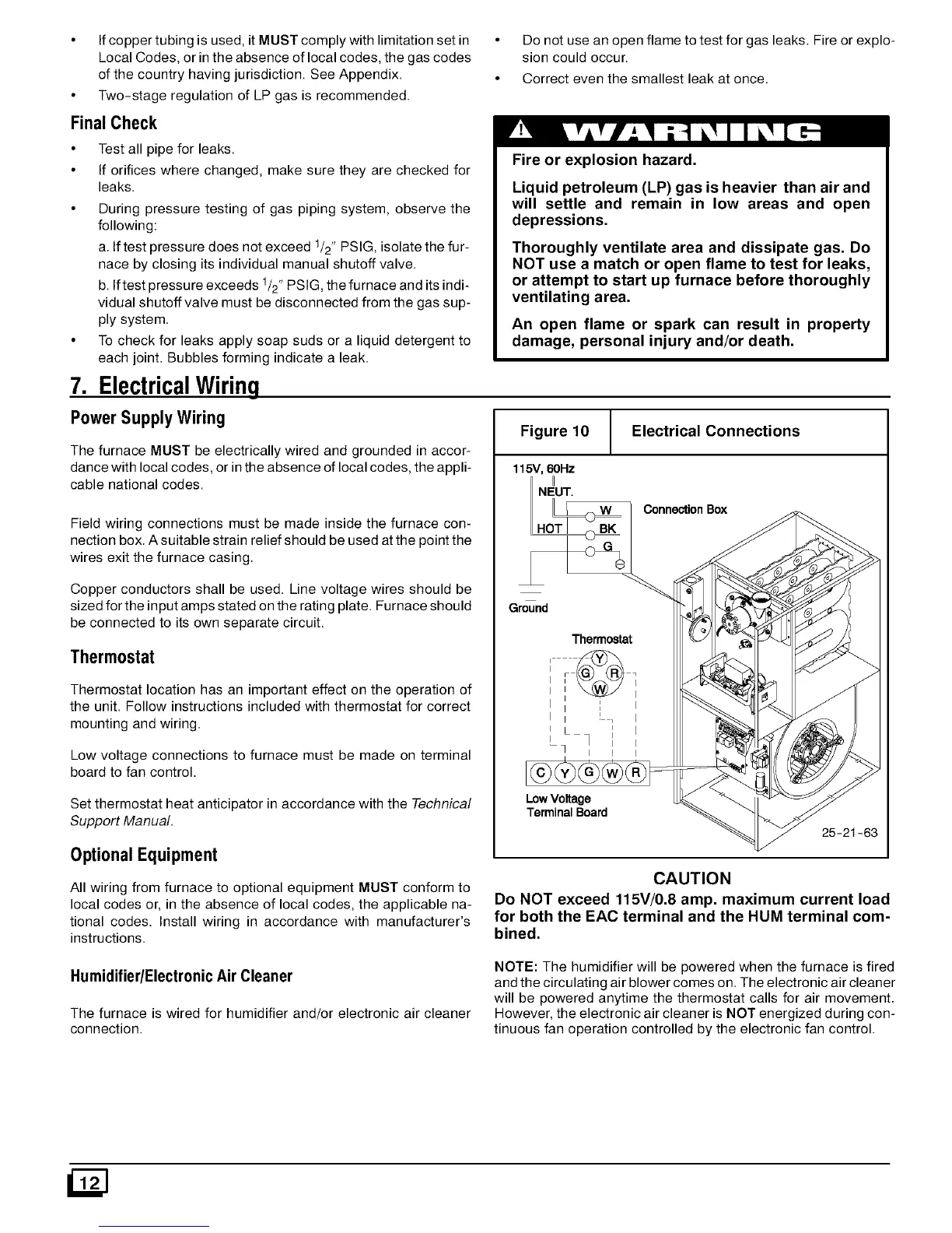
Figure 10 I Electrical Connections
115V, 60Hz
I
NEUT.
Field wiring connections must be made inside the furnace con-
nection box. A suitable strain relief should be used at the point the
wires exit the furnace casing.
Copper conductors shall be used. Line voltage wires should be
sized for the input amps stated on the rating plate. Furnace should
be connected to its own separate circuit.
Thermostat
Thermostat location has an important effect on the operation of
the unit. Follow instructions included with thermostat for correct
mounting and wiring.
Low voltage connections to furnace must be made on terminal
board to fan control.
Set thermostat heat anticipator in accordance with the Technical
Support Manual.
Ground
LowVokage
Terminal Board
OptionalEquipment
All wiring from furnace to optional equipment MUST conform to
local codes or, in the absence of local codes, the applicable na-
tional codes. Install wiring in accordance with manufacturer's
instructions.
Connection Box
25-2t-63
CAUTION
Do NOT exceed 115V/0.8 amp. maximum current load
for both the EAC terminal and the HUM terminal com-
bined.
Humidifier/ElectronicAir Cleaner
The furnace is wired for humidifier and/or electronic air cleaner
connection.
NOTE: The humidifier will be powered when the furnace is fired
and the circulating air blower comes on. The electronic air cleaner
will be powered anytime the thermostat calls for air movement.
However, the electronic air cleaner is NOT energized during con-
tinuous fan operation controlled by the electronic fan control.
 Loading...
