CAUTION
If filters are only suitable for heating application, ad-
vise homeowner that filter size may need to be in-
creased if air conditioning is added.
Figure 12 [ Side Return Filter Rack
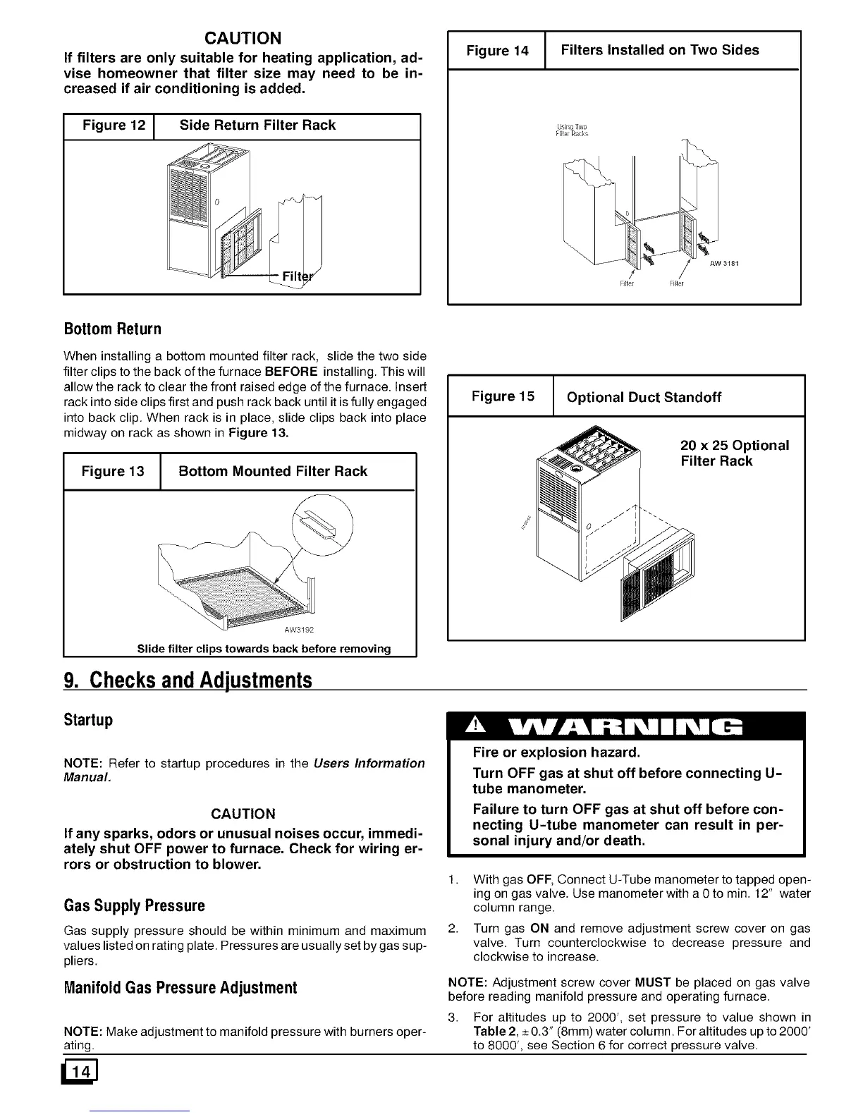
Figure 14 Filters Installed on Two Sides
Filter Filler
Bottom Return
When installing a bottom mounted filter rack, slide the two side
filter clips to the back of the furnace BEFORE installing. This will
allow the rack to clear the front raised edge of the furnace. Insert
rack into side clips first and push rack back until it is fully engaged
into back clip. When rack is in place, slide clips back into place
midway on rack as shown in Figure 13.
Figure 13 Bottom Mounted Filter Rack
=
AW3192
Slide filter clips towards back before removing
Checks and Adjustments
Figure 15
1
Optional Duct Standoff
20 x 25 Optional
Filter Rack
Startup
NOTE: Refer to startup procedures in the Users Information
Manual.
CAUTION
If any sparks, odors or unusual noises occur, immedi-
ately shut OFF power to furnace. Check for wiring er-
rors or obstruction to blower.
Gas Supply Pressure
Gas supply pressure should be within minimum and rnaximum
values listed on rating plate. Pressures are usually set by gas sup-
pliers.
Manifold Gas Pressure Adjustment
NOTE: Make adjustment to manifold pressure with burners oper-
ating.
Fire or explosion hazard.
Turn OFF gas at shut off before connecting U-
tube manometer.
Failure to turn OFF gas at shut off before con-
necting U-tube manometer can result in per-
sonal injury and/or death.
1. With gas OFF, Connect U-Tube manometer to tapped open-
ing on gas valve. Use manometer with a 0 to min. 12" water
column range.
2. Turn gas ON and remove adjustment screw cover on gas
valve. Turn counterclockwise to decrease pressure and
clockwise to increase.
NOTE: Adjustment screw cover MUST be placed on gas valve
before reading manifold pressure and operating furnace.
3. For altitudes up to 2000', set pressure to value shown in
Table 2, _+0.3" (8mm) water column. For altitudes up to 2000'
to 8000', see Section 6 for correct pressure valve.
 Loading...
