6. Removefourscrewsholdingtoppaneltocasing.Remove
toppanel.Discardtoppanel.Setscrewsaside.
7. Installdrafthoodassy.tocasingusingfourscrewspreviously
setaside.
8. Attachfieldconnectboxtodrafthoodassy.usingtwoscrews
previouslysetaside.
9. NTC5,NTN5&GNJSeriesfurnaces- Attachpressure
switchtodrafthoodassy.usingtwoscrewspreviouslyset
aside.
Vent Limit Switch Wiring (seeFigure6)
1. Locate wire harness assy. which is supplied with kit. Attach
terminals on one end of wire harness assy. to vent limit switch
located on draft hood assy.
2. Locate furnace's main limit. Detach wire with insulated termi-
nal from one side of main limit.
Route wire harness assy. from vent limit switch to main limit.
Attach female terminal of wire harness assy. to vacated main
limit terminal. Attach male terminal of wire harness assy. to
insulated terminal of wire previously detached from main lim-
it.
Completion of Installation
1. NTC5, NTN5 & GNJ Series furnaces - Locate Iouvered door
supplied with kit. Install on furnace.
2. Refer to installation instructions provided with furnace to put
the furnace into operation.
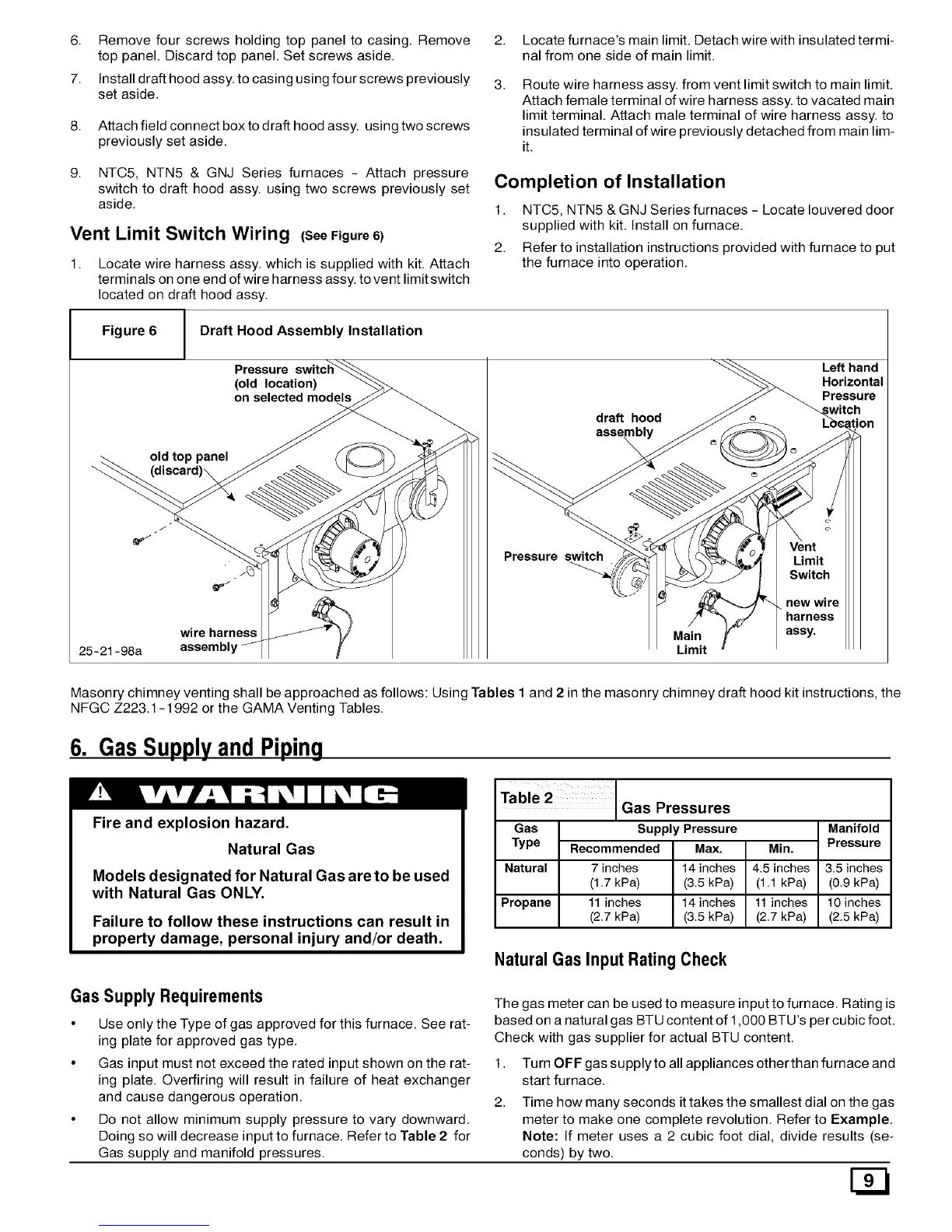
Figure 6 Draft Hood Assembly Installation
old top panel
(discard)\
Pressure
(old location)
on selected models
draft hood
assembl
Left hand
Horizontal
Pressure
J
Vent
Pressure switch Limit
Switch
new wire
harness
wire harness Main assy.
25-21-98a assembly Limit
Masonry chimney venting shall be approached as follows: Using Tables I and 2 in the masonry chimney draft hood kit instructions, the
NFGC Z223.1-1992 or the GAMA Venting Tables.
6. GasSupplyand Piping
Fire and explosion hazard.
Natural Gas
Models designated for Natural Gas are to be used
with Natural Gas ONLY.
Failure to follow these instructions can result in
property damage, personal injury and/or death.
Table 2
Gas
Type
Manifold
Pressure
Gas Pressures
supply Pressure
Recommended Max.
7 inches 14 inches
(1.7 kPa) (3.5kPa)
11 inches 14 inches
(2.7 kPa) (3.5kPa)
Min.
Natural 4.5 inches 3.5 inches
(1.1 kPa) (0.9 kPa)
Propane 11 inches 10 inches
(2.7 kPa) (2.5 kPa)
Natural Gas InputRating Check
Gas Supply Requirements
• Use only the Type of gas approved for this furnace. See rat-
ing plate for approved gas type.
• Gas input must not exceed the rated input shown on the rat-
ing plate. Overfiring will result in failure of heat exchanger
and cause dangerous operation.
• Do not allow minimum supply pressure to vary downward.
Doing so will decrease input to furnace. Refer to Table 2 for
Gas supply and manifold pressures.
The gas meter can be used to measure input to furnace. Rating is
based on a natural gas BTU content of 1,000 BTU's per cubic foot.
Check with gas supplier for actual BTU content.
1. Turn OFF gas supply to all appliances otherthan furnace and
start furnace.
2. Time how many seconds it takes the smallest dial on the gas
meter to make one complete revolution. Refer to Example.
Note: If meter uses a 2 cubic foot dial, divide results (se-
conds) by two.