Whenthefurnaceislocatedinanareanearoradjacenttotheliv-
ingarea,thesystemshouldbecarefullydesignedwithreturnsto
minimizenoisetransmissionthroughthereturngrille.Anyblower
movinga highvolumeofairwillproduceaudiblenoisewhich
couldbeobjectionabletowhentheunitislocatedveryclosetoliv-
ingareas.Itisadvisabletoroutethereturnairductsunderthe
floororthroughtheattic.
1. Forsideconnectionsusinga16"x25"filter,cutouttheem-
bossedareashowninFigure30.Thiswillprovidea141/2"
x221/2"approximateopening.
SideReturnAir Cutout
HHHHHHHHHHHHHHHHHHHHHHHHHHHHHHHHHHHHHHHHHHHHHHHHHHHHHHHHHHHH
= 141/2"Height of Cutout for 16" x 25" Filter j
221/2"Width of Cutout for 16" x 25" Filte_
J
Embossed Area
on Side of Furnace
A
11>
Furnace
Bottom
NOTE: A 125,000 Btuh furnace requires two side returns or a bot-
tom return for 5 tons cooling. If two side returns are used it does
NOT allow the condensate drain line to be run out the side of fur-
nace. If line MUST be run out the side, an optional standoff filter
rack with one 20x25x1 filter is needed. Install optional filter rack
on side of furnace opposite the side where condensate drain line
will exit.
2.
3.
4.
Bottom returns can be made by removing the knockout
panel in the furnace base. Do NOT remove knock-out ex-
cept for a bottom return. A 20" x 25" filter can be used for a
bottom return for a100,000 Btu hfurnace. A 25" x 25" filter is
required for 125,000 Btuh furnaces.
An optional 20"x 25" duct standoff (NAHAOO1TK) is avail-
able to be used in lieu of one filter on each side of furnace.
Installation of locking-type dampers are recommended in
all branches, or in individual ducts to balance system's air
flow.
5. Non-combustible, flexible duct connectors are recom-
mended for return and supply connections to furnace.
6. If air return grille is located close to the fan inlet, install at
least one, 90 ° air turn between fan and inlet grille to reduce
noise.
NOTE: To further reduce noise, install acoustical air turning vanes
and/or line the inside of duct with acoustical material.
Sizing
Existing or new ductwork MUST be sized to handle the correct
amount of airflow for either heating only or heating and air condi-
tioning.
Insulation
1. Insulate ductwork installed in attics or other areas exposed
to outside temperatures with a minimum of 2" insulation
and vapor barrier.
2. Insulate ductwork in indoor unconditioned areas with a
minimum of 1" insulation with indoor type vapor barrier.
Filters
A Filter must be used:
Filters are not supplied with these furnaces, but can be purchased
from dealer.
Use either filter type:
• Washable, high velocity filters are based on a maximum
air flow rating of 600 FPM.
• Disposable, low velocity filters are based on a maximum
air flow of 300 FPM when used with filter grille.
NOTE: Disposable, low velocity filters may be replaced with
washable, high velocity filter providing they meet the minimum
size areas. Washable, high velocity filters can be replaced ONLY
with same type and size.
Side Mou nted Filter Rack
/d °
/
/ I
25-20-90
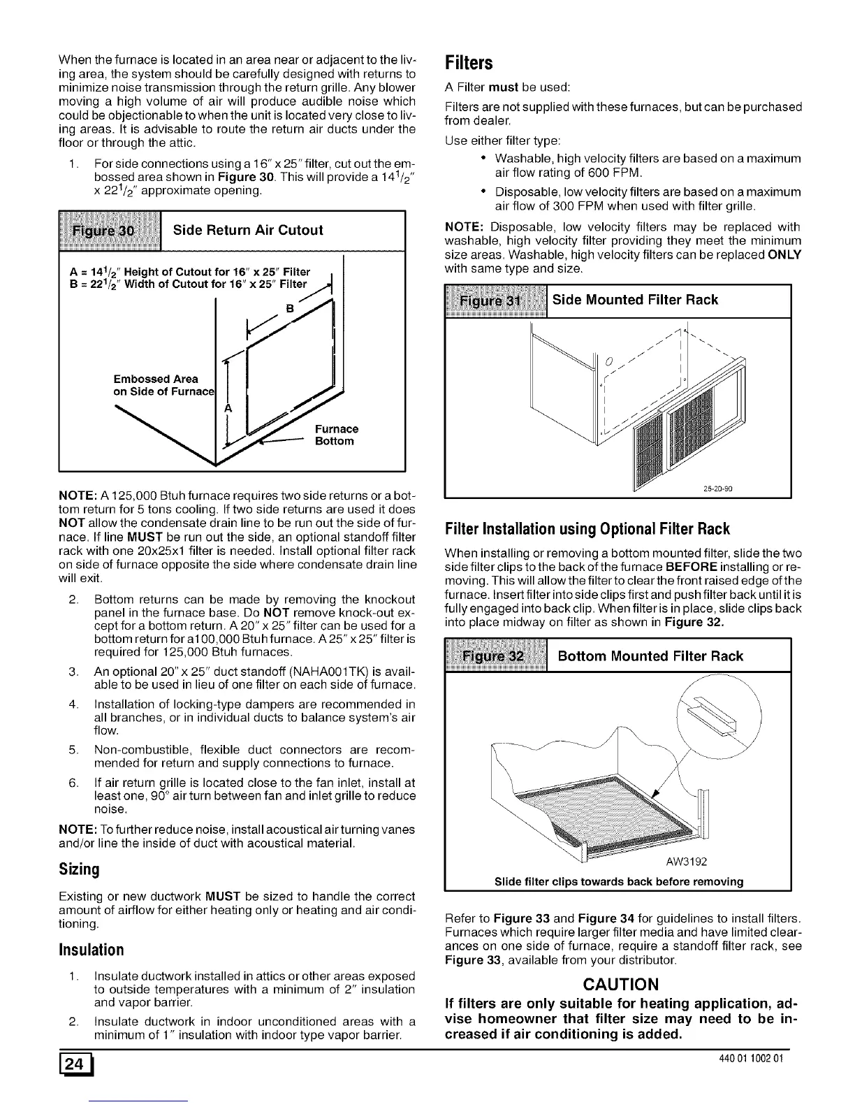
Filter Installation using Optional Filter Rack
When installing or removing a bottom mounted filter, slide the two
side filter clips to the back of the fu mace BEFORE installing or re-
moving. This will allow the filter to clear the front raised edge of the
furnace. Insert filter into side clips first and push filter back until it is
fully engaged into back clip. When filter is in place, slide clips back
into place midway on filter as shown in Figure 32.
Bottom Mounted Filter Rack
....... _ J
_iiiiiiiiiiiiiiiiiiiiiiii%
AW3192
Slide filter clips towards back before removing
Refer to Figure 33 and Figure 34 for guidelines to install filters.
Furnaces which require larger filter media and have limited clear-
ances on one side of furnace, require a standoff filter rack, see
Figure 33, available from your distributor.
CAUTION
If filters are only suitable for heating application, ad-
vise homeowner that filter size may need to be in-
creased if air conditioning is added.
[_ 440 01 100201
 Loading...