3. Combustion&VentilationAir
Poison carbon monoxide gas Hazard.
Use methods described here to provide combustion
and ventilation air.
Failure to provide adequate combustion and ven-
tilation air can result in death and/or personal injury.
Ventingand CombustionAir Check
NOTE: The following information is supplied to allow the installer
to make adjustments to the setup of existing appliances, IF
REQUIRED, based on good trade practices, local codes, and
good judgement of the installer. Manufacturer does NOT take re-
sponsibility for modifications made to existing equipment.
NOTE: If this installation removes an existing furnace from a
venting system serving one or more other appliances, and to
make sure there is adequate combustion air for all appliances,
MAKE THE FOLLOWING CHECK.
1. Seal any unused openings in the venting system.
2. Visually inspect the venting system for proper size and hor-
izontal pitch to ensure there is no blockage or restriction,
leakage, corrosion or other deficiencies which could cause
an unsafe condition.
3. Insofar as is practical, close all doors and windows and all
doors between the space in which the appliance(s) remain-
ing connected to the venting system are located and other
spaces of the building.
4. Turn on clothes dryers and any appliance not connected to
the venting system. Turn on any exhaust fans, such as
range hoods and bathroom exhausts, so they will operate
at maximum speed. Do not operate a summer exhaust fan.
Close fireplace dampers.
5. Follow the lighting instructions for each appliance being in-
spected. Adjust thermostat so appliance(s) will operate
continuously.
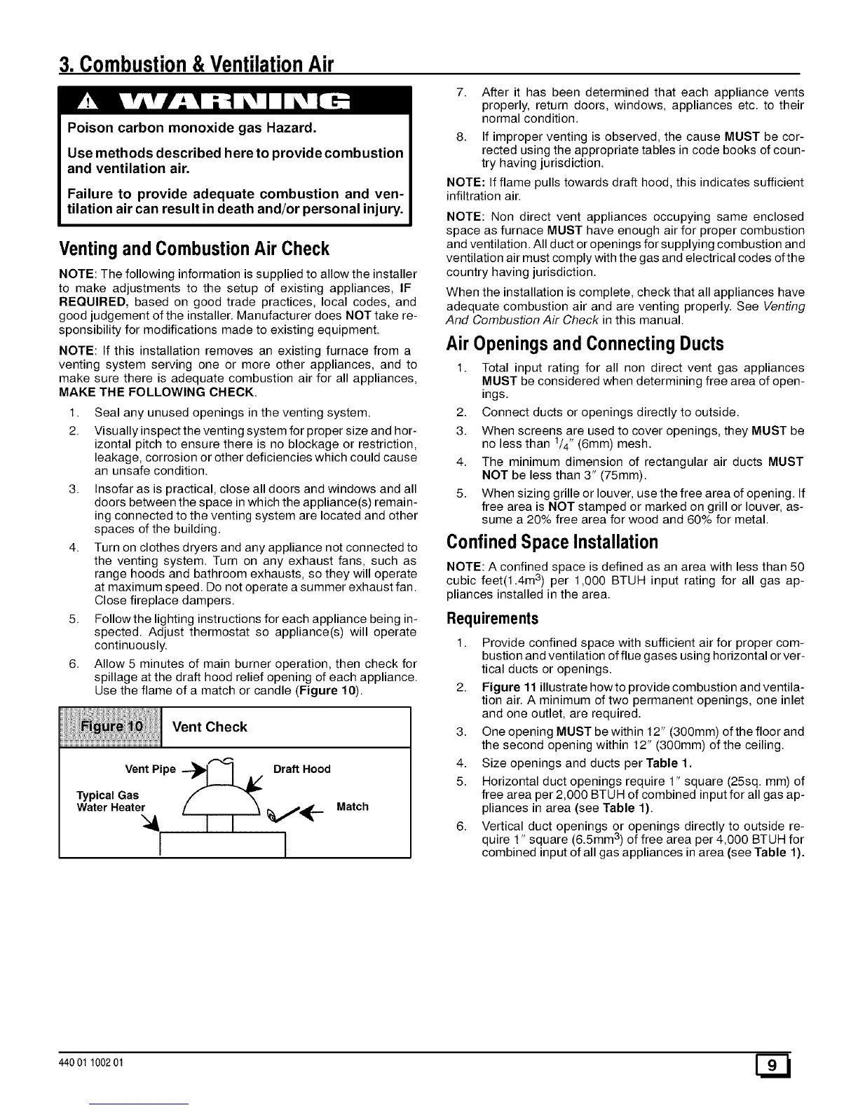
6. Allow 5 minutes of main burner operation, then check for
spillage at the draft hood relief opening of each appliance.
Use the flame of a match or candle (Figure 10).
Vent Check
Vent Pipe ---_t I A/ Draft Hood
Typical Gas
Water Heate_;_l / ] i _ V'_'-
Match
7. After it has been determined that each appliance vents
properly, return doors, windows, appliances etc. to their
normal condition.
8. If improper venting is observed, the cause MUST be cor-
rected using the appropriate tables in code books of coun-
try having jurisdiction.
NOTE: If flame pulls towards draft hood, this indicates sufficient
infiltration air.
NOTE: Non direct vent appliances occupying same enclosed
space as furnace MUST have enough air for proper combustion
and ventilation. All duct or openings for supplying combustion and
ventilation air must comply with the gas and electrical codes of the
country having jurisdiction.
When the installation is complete, check that all appliances have
adequate combustion air and are venting properly. See Venting
And Combustion Air Check in this manual.
Air Openingsand ConnectingDucts
1. Total input rating for all non direct vent gas appliances
MUST be considered when determining free area of open-
ings.
2. Connect ducts or openings directly to outside.
3. When screens are used to cover openings, they MUST be
no less than 1/4" (6mm) mesh.
4. The minimum dimension of rectangular air ducts MUST
NOT be less than 3" (75mm).
5. When sizing grille or louver, use the free area of opening. If
free area is NOT stamped or marked on grill or louver, as-
sume a 20% free area for wood and 60% for metal.
ConfinedSpaceInstallation
NOTE: A confined space is defined as an area with less than 50
cubic feet(1.4m 3) per 1,000 BTUH input rating for all gas ap-
pliances installed in the area.
Requirements
1. Provide confined space with sufficient air for proper com-
bustion and ventilation of flue gases using horizontal or ver-
tical ducts or openings.
2. Figure 11 illustrate howto provide combustion and ventila-
tion air. A minimum of two permanent openings, one inlet
and one outlet, are required.
3. One opening MUST be within 12" (300mm) of the floor and
the second opening within 12" (300mm) of the ceiling.
4. Size openings and ducts per Table 1.
5. Horizontal duct openings require 1" square (25sq. mm) of
free area per 2,000 BTUH of combined input for all gas ap-
pliances in area (see Table 1).
6. Vertical duct openings or openings directly to outside re-
quire 1" square (6.5mm 3) of free area per 4,000 BTUH for
combined input of all gas appliances in area (see Table 1).
440 01 100201 [_
 Loading...